

You bought a 2024 Ford F-250 Super Duty for its work-ready capability, but the factory upfitter switches feel like a mystery. Six blank buttons stare at you from the overhead console while your dash cam, light bar, and two-way radio sit uninstalled in the garage. The wires are hidden behind panels, the labels look like alphabet soup, and one wrong connection could melt a factory harness or void your warranty.
This guide gives you exact locations, verified wire specs, and step-by-step methods straight from Ford documentation and confirmed owner experiences. You will learn where the pass-through wires hide under the glove box, why the 22AWG wire cannot handle a 15A fuse, and how to trigger a relay for high-draw accessories. By the final section, you will wire any accessory with confidence and keep your truck’s electrical system intact.
Locate the Under-Hood Upfitter Fuse Box

The under-hood fuse box is the brain of your upfitter system and the starting point for every wiring project.
Access the Passenger-Side Fuse Box
The upfitter fuse box sits above the passenger-side wheel well, separate from the larger battery junction box. To open it:
1. Stand at the front of the truck and face the passenger fender.
2. Find the smaller rectangular black box secured with two plastic clips.
3. Press the center of each clip inward to release the housing.
4. Lift the entire box straight up to expose the wire bundles underneath.
Do not confuse this unit with the main power distribution box near the battery. The upfitter box is smaller, labeled for auxiliary circuits, and contains only the relays and fuses tied to your dash switches.
Identify the Output and Pass-Through Bundles
Once the cover is off, you will see two distinct wire groups exiting the bottom:
– Switch Output Bundle: Six wires (Switches 1 through 6) that deliver 25A ignition-switched power to engine bay accessories like compressors or light bars.
– Pass-Through Bundle: A taped group of four thinner wires designed to route switched power into the cabin for interior devices.
These bundles often sit side by side but serve completely different purposes. The pass-through wires are 18AWG and 22AWG, far too thin for high-current loads. Label both bundles with painter’s tape before you start any work.
Find the Interior Pass-Through Wires
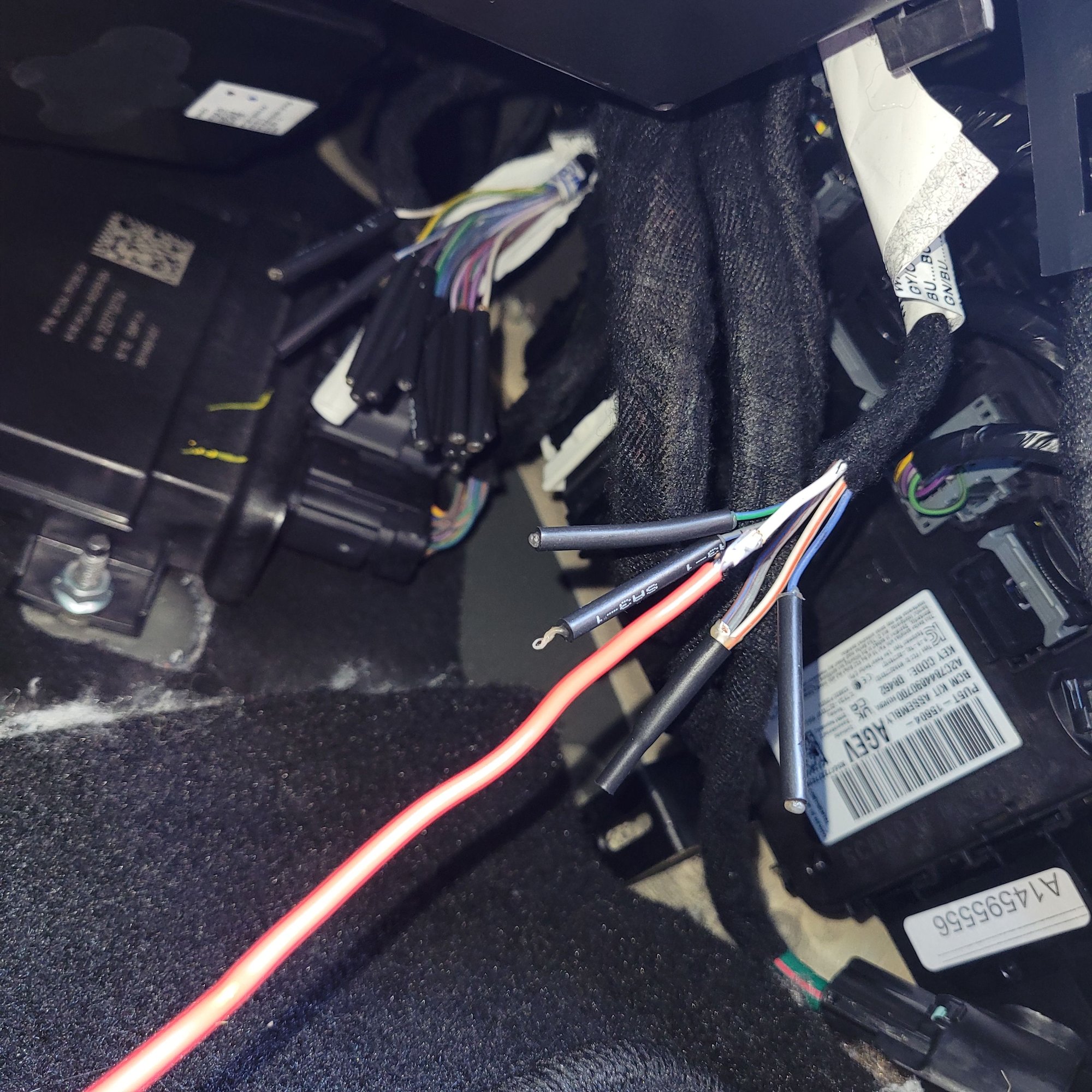
For cabin accessories like dash cams and radios, the pass-through wires eliminate the need to drill through your firewall.
Remove the Glove Box Carpet Panel
Only one panel stands between you and the wires:
1. Open the passenger glove box and lower it fully.
2. Locate the rectangular carpeted panel directly below the glove box opening.
3. Insert a plastic pry tool along the edge and gently unclip the panel.
4. Set the panel aside; no screws or bolts are involved.
This exposes the passenger footwell and the interior fuse box area. Work slowly to avoid cracking the plastic clips.
Locate the Taped Wire Loop
With the panel removed, look to the driver’s side of the interior fuse box. You will find a large grey connector mounted there. The pass-through wires are wrapped underneath this connector in a taped loop, often secured with zip ties and tucked toward the kick panel.
The bundle contains four wires total: three 18AWG and one 22AWG. They carry printed alphanumeric codes instead of color labels, so a multimeter is mandatory for identification.
Understand Wire Gauge and Amperage Limits
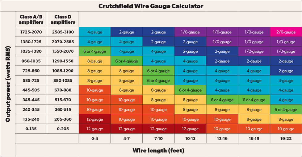
The gauge mismatch between under-hood fuses and interior wires is the most common cause of upfitter wiring failures.
Check Wire Gauge Before Connecting Any Load
The pass-through bundle is rated for far less current than the fuses protecting it:
– Three 18AWG wires: Safe for roughly 10A continuous load.
– One 22AWG wire: Safe for about 5A maximum.
The under-hood fuses are rated up to 25A, but the smallest available fuse is 15A. In a dead short, a 15A fuse may not blow fast enough to protect 18AWG or 22AWG wiring. Never connect loads exceeding 10A directly to the pass-through bundle.
Use Relays for High-Draw Accessories
To safely run devices drawing more than 5 to 10A:
1. Connect the pass-through wire to the coil terminal of a 30A or higher relay.
2. Wire the relay’s power input directly to the battery or a high-amperage source.
3. Connect your accessory to the relay’s output terminal.
This setup uses the factory wire only as a low-current trigger signal, eliminating any risk to the thin interior wiring. This method works perfectly for inverters, high-output LED bars, or winches.
Connect Interior Accessories Safely
The pass-through wires are ideal for low-draw electronics commonly installed in fleet and personal trucks.
Wire Dash Cams and Radios Correctly
For dash cams, GPS units, or two-way radios:
1. Use a multimeter to identify which pass-through wire matches your target switch.
2. Strip ¼ inch of insulation from the selected wire using a precision stripper.
3. Connect the accessory’s positive lead with a quality tap connector or a soldered joint.
4. Ground the accessory to a clean metal point in the cabin, such as a bolt near the fuse box.
Keep total current draw under 2.4A for dash cams and under 5A for mobile radios. If your radio pulls 15A or more on transmit, use the pass-through wire only to trigger an external relay mounted near the battery.
Avoid Common Grounding Mistakes
The pass-through bundle contains no ground wire. You must supply your own:
– Use a ring terminal connected to a factory grounding stud.
– Scrape paint off metal surfaces for a solid connection.
– Keep ground wires as short as possible to reduce resistance.
Poor grounding causes voltage drops, erratic accessory behavior, and potential damage to sensitive electronics.
Power Under-Hood Accessories Directly
For maximum current capacity, high-amperage devices should connect at the engine bay fuse box.
Tap Into the Switch Output Wires
To power compressors, fog lights, or work lamps:
1. Access the switch output bundle hanging from the bottom of the upfitter fuse box.
2. Select the wire corresponding to the dash switch you want to control.
3. Use a weatherproof tap connector or soldered splice to join your accessory wire.
These wires are protected by 25A fuses and built with proper gauge for full relay output. Always fuse your accessory wire within 18 inches of the power source as a secondary safety measure.
Match Each Switch to Its Function
Label every output wire for easy troubleshooting later:
– Switch 1: Often used for radio push-to-talk or emergency lights.
– Switch 2: Ideal for air compressors.
– Switch 3: Commonly assigned to forward-facing light bars.
– Switches 4 through 6: Reserved for bed equipment or backup systems.
Use heat-shrink tubing and printed labels to keep everything organized, especially when running multiple accessories.
Identify Switch Functions With a Multimeter
The printed codes on the pass-through wires do not tell you which switch they control, so testing is required.
Test for Ignition-Switched Voltage
Set your multimeter to DC voltage:
1. Turn the ignition to the “On” or “Accessory” position; the engine does not need to run.
2. Place the black probe on a known ground, such as a bolt on the fuse box.
3. Touch the red probe to each wire in the pass-through bundle.
4. Toggle each upfitter switch and note which wire shows 12V when activated.
A wire that reads 12V only when a specific switch is on is confirmed as that switch’s ignition-switched output. Repeat the process for all six switches if you plan to use multiple circuits.
Verify Continuity to Prevent Errors
After identifying each function:
1. Turn off the ignition completely.
2. Switch your multimeter to continuity mode (the beep setting).
3. Probe from the interior pass-through wire to its matching under-hood output wire.
4. Listen for an audible beep to confirm a closed circuit with no breaks.
This step prevents miswiring and confirms the entire path from relay to cabin is intact before you connect any accessory.
Avoid SEIC and PTO Wiring Conflicts
Fleet modifications like snow plows and dump beds use a different system that can interfere with your upfitter switches.
Differentiate the Upfitter Harness From the SEIC Harness
The upfitter harness controls your six dash switches. The SEIC (Standard Equipment Installation Circuit) is a separate system for major aftermarket installations.
Key differences:
– The SEIC uses a dedicated connector near the main harness.
– BD Diesel and similar performance kits connect to the SEIC, not the upfitter wires.
– Installing a SEIC kit may require removing specific upfitter control wires, which disables those switches.
Always verify which harness you are modifying. Cutting SEIC wires by mistake can disable critical factory systems and trigger warning lights.
Preserve Pass-Through Function After a SEIC Install
If a SEIC module takes control of an upfitter switch:
– The matching pass-through wire may no longer respond to the dash switch.
– To restore function, splice the original upfitter output back into the circuit or install a Y-harness splitter.
– Alternatively, reassign that switch’s function through the SEIC module’s programming if supported.
Consult the Ford Body Builders Layout Book (BBLM) on Page 113 for wiring diagrams showing the exact separation points between SEIC and upfitter circuits.
Follow Best Practices for Long-Term Reliability
A clean installation keeps your upfitter system safe and functional for years.
Use Ford’s Body Builders Layout Book
The Ford BBLM is the definitive resource for upfitter wiring:
– Access it online through Ford’s commercial vehicle portal.
– Navigate to Page 113 for upfitter switch schematics.
– Use the diagrams to verify wire codes, relay locations, and fuse assignments.
This document resolves conflicting dealer advice and confirms factory specifications down to the last detail.
Prevent Corrosion at Every Connection
The footwell environment exposes wires to moisture and temperature swings:
– Seal all splices with adhesive-lined heat shrink tubing.
– Apply dielectric grease to every connector.
– Route wires away from HVAC vents and floor drain channels.
Blunt-cut factory wires fray easily. Solder and seal every connection for maximum durability.
Prioritize Factory-Approved Methods
Using the pass-through wires is Ford’s recommended installation method:
– It does not void your warranty when done correctly.
– It avoids tampering with primary vehicle harnesses.
– It maintains OEM electrical integrity.
Avoid hacking into random factory bundles. The upfitter system exists specifically to give you a warranty-safe path for accessory power.
Frequently Asked Questions About 2024 F250 Upfitter Switch Wiring
Where exactly are the pass-through wires located in a 2024 F250?
The pass-through wires are inside the passenger cabin, tucked beneath the glove box. Remove the carpeted panel below the glove box opening, then look on the driver’s side of the interior fuse box. You will find a taped loop of four wires wrapped underneath a large grey connector.
Can I power a light bar directly from the pass-through wires?
No. The pass-through wires are only 18AWG and 22AWG, rated for roughly 5 to 10 amps. A light bar typically draws more current than these wires can safely handle. Use the pass-through wire to trigger a relay, then power the light bar through the relay from a heavier source or directly from the under-hood switch output wires.
What gauge are the 2024 F250 upfitter pass-through wires?
The bundle contains three 18AWG wires and one 22AWG wire. The 18AWG wires handle about 10 amps continuous, while the 22AWG wire is limited to roughly 5 amps. Despite being protected by fuses rated up to 25 amps under the hood, these thinner wires create a bottleneck that requires relay-based solutions for high-draw accessories.
Will installing accessories through the upfitter switches void my warranty?
No, not when you use the factory pass-through wires correctly. Ford designed the upfitter system specifically for aftermarket accessory integration. As long as you respect the wire gauge limits, use proper connections, and avoid cutting into unrelated harnesses, your warranty remains intact.
How do I tell which upfitter switch controls which wire?
Use a multimeter set to DC voltage. With the ignition in the “On” or “Accessory” position, probe each wire in the pass-through bundle while toggling each dash switch. The wire that shows 12V only when a specific switch is activated is that switch’s output. Always verify with a continuity check before final installation.
What is the difference between upfitter switches and SEIC wiring?
Upfitter switches control six auxiliary outputs through the dash panel and are designed for general accessories. The SEIC (Standard Equipment Installation Circuit) is a separate harness for fleet equipment like snow plows and dump beds. SEIC kits may override or disable certain upfitter switches, so always confirm which system you are modifying before cutting any wires.
Key Takeaways for Wiring Your 2024 F250 Upfitter Switches
The 2024 F-250 upfitter system delivers convenient, switchable power when you respect its limits. Always locate the pass-through wires under the passenger glove box, verify every function with a multimeter, and use relays for any load over 5 amps. Differentiate the upfitter harness from the SEIC and PTO systems before cutting anything, and reference the Ford BBLM on Page 113 for official schematics. For high-draw devices, tap into the under-hood output wires directly to access the full 25A capacity. Grab your multimeter, pull that carpet panel, and start mapping your switches today; your truck is ready to become a fully customized command center without risking electrical damage or warranty issues.


