

If your 1994 F150 speedometer isn’t working, you’re not alone. This is one of the most common electrical issues reported across forums, repair shops, and Ford communities. The speedometer either dies completely, acts erratically, or stops while other gauges remain functional. Often, it’s accompanied by hard shifting, a blinking overdrive light, or even blown fuses. Unlike older trucks with mechanical cables, the 1994 Ford F-150 uses an electronic speedometer system, which means your fix won’t be as simple as replacing a spinning cable.
This guide walks you through the exact steps to identify and repair the real cause, whether it’s a $15 fuse or a failed internal circuit. We’ll cover symptoms, testing procedures, common traps, and the most likely culprits based on real-world data. By the end, you’ll know exactly where to look and how to get your speedometer and transmission back to normal.
Check Fuse 18 and Fuse 8 First
Before tearing into sensors or clusters, check the fuses, especially Fuse 18 (10A) and Fuse 8 (15A) in the interior fuse panel under the dash. These small circuits power the entire speedometer system and often blow due to hidden shorts. Fuse 18 powers the instrument cluster, ABS, airbag, and speedometer, while Fuse 8 provides constant battery voltage to the cluster.
A blown Fuse 18 is a frequent symptom and a major clue. But don’t just look at the fuse. Use a multimeter or fuse tester. Many fuses appear intact but have internal breaks.
Test Fuses with a Multimeter
- Pull Fuse 18 and Fuse 8 using a fuse puller
- Set your multimeter to continuity or resistance mode
- Touch probes to both metal ends
- If no beep or infinite resistance, the fuse is dead
If either fuse is blown, replace it, but don’t stop there. A recurring blowout means something downstream is shorting the circuit. Common culprits include a failed airbag control module, shorted ABS module, or damaged wiring near the cluster.
Test Power at the Instrument Cluster
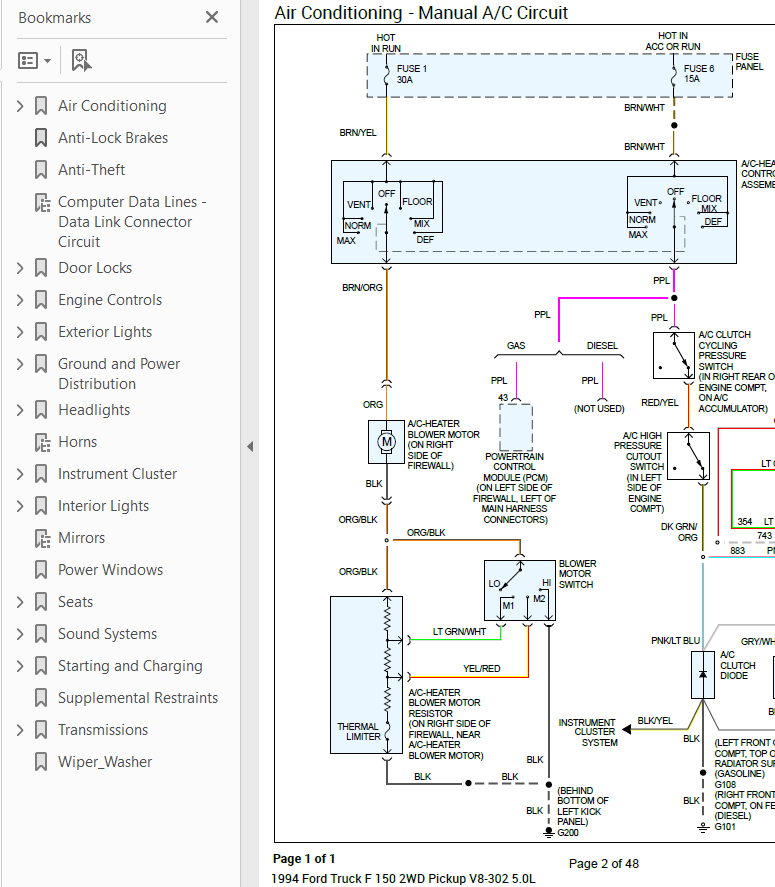
If fuses are good, verify power is reaching the instrument cluster. The cluster gets power through a 12-pin connector on the back. You’ll need to partially remove the dash trim to access it, but you don’t need to pull the cluster yet.
Check Key Pins with a Multimeter
• Pin 1 (Light Green/Yellow): Should show 12V constant (from Fuse 8)
• Pin 3 (White/Violet or White/Purple): Should show 12V only in RUN position (from Fuse 18)
• Pin 2 (Pink/Orange): Ground. Test for continuity to chassis
No power at these pins means you need to confirm fuses are truly good, check ignition switch output for switched power, and inspect wiring from fuse panel to cluster for cuts or corrosion.
Look for the Blinking O/D Light
If your overdrive light blinks when you shift into drive, that’s not just a transmission quirk. It’s a diagnostic signal. The PCM uses this to tell you it’s not getting a speed signal.
Why It Happens
The PCM needs vehicle speed data to time automatic shifts, engage torque converter lockup, and activate overdrive. When the speed signal drops out, the PCM defaults to fail-safe mode, which increases line pressure causing hard 1-2 and 2-3 shifts, disables overdrive so the light blinks, and may limit engine power.
Blinking O/D plus dead speedometer almost certainly means a VSS signal loss to the PCM.
Test the VSS Signal at the Cluster
The Vehicle Speed Sensor is on the rear differential and sends an AC signal to the instrument cluster. But replacing the VSS first is a common mistake. Many owners do it and still have no speed because the problem is often downstream.
Verify the Signal at the Source
Go to the 12-pin cluster connector and test Pin 4 (Red/Pink) for VSS signal input and Pin 5 (Light Green/Black) for signal ground. Set your multimeter to AC voltage. Have an assistant drive the truck at 20-30 mph while you measure between Pin 4 and Pin 5.
Expected Results
At 10 mph, expect approximately 0.5V AC. At 30 mph, expect approximately 1.5V AC. At 50 mph, expect approximately 2.5V AC.
Signal increases with speed means the VSS and wiring are good, and the cluster or PSOM is faulty. No signal means the problem is upstream, involving the VSS, wiring, or ABS short.
Test the VSS Sensor Directly
If no signal reaches the cluster, remove the VSS from the rear differential and test it directly.
How to Test the VSS
- Unplug the 2-wire connector
- Remove the sensor with a 10mm socket
- Connect multimeter in AC voltage mode across the two terminals
- Spin the sensor gear with a drill or your fingers
Output should increase with spin speed, ranging from 0.2V to 3V AC. Resistance should read 800-1,400 ohms. If no voltage, erratic spikes, or resistance is out of range, replace the sensor. Use Motorcraft or Dorman and avoid cheap no-name brands.
Disconnect the ABS Module to Rule Out Shorts
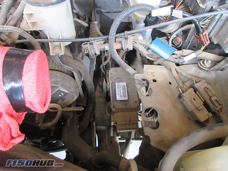
Here’s a fast, free test most overlook: unplug the ABS module and see if the speedometer comes back. The ABS module shares the VSS signal. If it develops an internal short, it can pull down the entire signal line, killing the speedometer, even if the VSS is fine.
How to Test
- Locate the ABS module behind the glove box (passenger side)
- Remove the glove box or lower dash panel
- Unplug the large electrical connector
- Start the truck and drive 10-15 mph
If the speedometer works, the ABS module is shorting the circuit and needs replacement. If there’s no change, the problem is elsewhere.
Diagnose a Failed PSOM or Cluster

If fuses are good, power and ground are confirmed at the cluster, VSS signal reaches Pin 4, but speedometer and odometer are dead, the PSOM inside the cluster has failed. PSOMs die due to age (25+ years of thermal cycling), moisture from cowl leaks, voltage spikes from jump-starts or alternator issues, and internal circuit degradation.
Confirming PSOM Failure
No odometer display, the needle doesn’t move, and all other cluster functions (fuel, temp, tach) may work fine while AC signal is present at Pin 4 but not processed.
There’s no DIY repair for a dead PSOM unless you’re a circuit board technician. Your options include replacing with a remanufactured cluster (programmed to your mileage), sending to a specialty repair shop, or buying a used cluster that must be programmed to your VIN and mileage.
Inspect Wiring and Grounds
Even with good fuses and sensors, bad wiring or grounds can kill the signal. Check the VSS to cluster harness for chafed, pinched, or rodent-damaged wires. Clean the ground at the cluster and ensure solid chassis connection. Inspect the firewall pass-through where wires near the brake booster or transmission tunnel often rub.
Use a wiring diagram to trace the Red/Pink wire for VSS signal to cluster and the Light Green/Black wire for signal ground. Test continuity between VSS connector and cluster Pin 4. Any break or high resistance means repair is needed.
Address Blown Fuses Caused by Airbag Module
One often-missed cause is the airbag control module. It shares Fuse 18 with the speedometer and ABS. If it fails shorted, it can repeatedly blow the fuse, taking out the speedometer.
How to Diagnose
Fuse 18 blows immediately after replacement, the airbag light may be on or flashing. Disconnect the airbag module connector under the dash on the passenger side, replace the fuse, and if it stays intact, the airbag module is shorted.
Most Likely Causes Ranked
Based on real-world data and technician reports, here’s the likelihood of each cause.
• Failed PSOM/Cluster: Most Common. Signal at Pin 4 but no display.
• Blown Fuse 18: Frequent. Fuse dead, may recur.
• Shorted ABS Module: Moderate. Speedometer works when unplugged.
• Failed Airbag Module: Less Common. Repeated fuse blowouts.
• Bad VSS Sensor: Less Common. No AC output when spun.
• Wiring Damage: Rare. Intermittent signal with visible damage.
Final Repair Checklist
Use this sequence to diagnose fast and avoid wasted parts.
- Check Fuse 18 and Fuse 8 (test, don’t guess)
- Test power at cluster (Pins 1 and 3)
- Look for blinking O/D light
- Test VSS signal at Pin 4 while driving
- If signal present, replace cluster/PSOM
- If no signal, test VSS directly
- Disconnect ABS module. Does speed return?
- Inspect wiring and grounds
- Check airbag module if fuse keeps blowing
Frequently Asked Questions About 1994 F150 Speedometer Not Working
Why does my speedometer not work but my odometer does?
This typically indicates a problem with the speedometer needle mechanism itself or the stepper motor inside the cluster. The PSOM may still be processing the signal for the odometer but failing to drive the analog needle. A cluster replacement or repair is usually needed.
Can a bad VSS cause hard shifting?
Yes. The PCM relies on VSS signal to control transmission shift timing and torque converter lockup. When the signal is lost, the PCM defaults to fail-safe mode, causing harsh shifts and disabling overdrive.
Is there a way to test the speedometer without driving?
You can test the VSS sensor directly by removing it from the differential and spinning the gear with a drill while measuring AC voltage output. This verifies if the sensor is generating a signal.
Will a used cluster from a salvage yard work?
Clusters from salvage yards often need reprogramming to match your VIN and mileage. Simply plugging in a used cluster typically won’t work. Budget for programming costs or consider a remanufactured unit.
Can I drive without a working speedometer?
You can physically drive the truck, but the transmission will likely shift harshly due to the PCM in fail-safe mode. The O/D light will blink, and you may experience poor fuel economy. It’s not recommended for long-term driving.
Key Takeaways for Fixing Your 1994 F150 Speedometer
The 1994 F150 speedometer not working issue is almost always electrical, not mechanical. The PSOM inside the instrument cluster is the most common failure point, followed by blown Fuse 18 and shorted ABS modules. By following this guide’s diagnostic sequence, you’ll skip the guesswork and fix the real problem. Most repairs take 1-3 hours and cost under $200. Test the VSS signal at the cluster before replacing any sensors. Once the speed signal is restored, your transmission will shift smoothly again. Don’t throw parts at it. Diagnose it right.


