
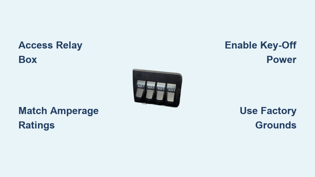
Owning a Ford F-350 Super Duty gives you access to factory-installed AUX switches that control heavy-duty accessories without messy cabin wiring. These upfitter switches use low-current signals to trigger high-amperage relays under the hood, keeping your cab safe while powering winches or LED lights.
This guide explains exactly how to use AUX switches in F-350 trucks to install dash cams, rock lights, and air compressors professionally. You will learn circuit ratings, key-off power modifications, and proper grounding techniques to avoid battery drain or electrical damage.
Access the Under-Hood Relay Box Safely
Proper installation begins with full access to the under-hood relay box located near the passenger-side firewall. This unit houses the relays and fuses that manage power delivery for all upfitter circuits.
Steps to Remove the Relay Box
- Disconnect the negative battery terminal to prevent accidental shorts.
- Depress the two locking tabs on the back of the relay box housing.
- Remove the 10mm nut securing the box to the chassis.
- Unplug the main electrical connector found near the AC line.
- Set the box on a stable surface like the air intake tube for 360-degree access.
Pro Tip: On diesel models, remove the passenger-side battery tray to create space for under-tray wire routing. If the battery remains connected, cover the positive terminal with a rubber glove to prevent accidental grounding.
Identify Switch Circuits and Amperage Ratings
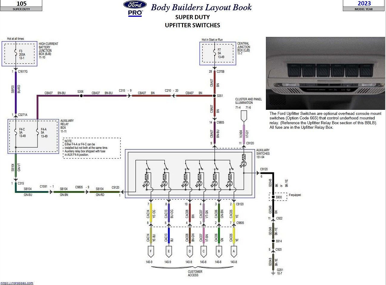
Each AUX switch in your cab corresponds to a specific fused circuit under the hood. Matching your accessory to the correct amperage rating prevents overloads and ensures system longevity.
Match Your Accessory to Circuit Capacity
- Switch 1 (40A): Best for winches and large LED light bars.
- Switch 2 (25A): Ideal for air compressors and cooling fans.
- Switches 3-4 (20A): Perfect for GPS units and dash cams.
- Switches 5-6 (Modifiable): Can be configured for key-off power up to 240A.
Read the Color Code Label
Take a photo of the color code label on the relay box before disconnecting anything. This label identifies terminal numbers, wire colors like Green/Brown for Relay 1, and circuit behavior. Cross-reference this with your owner’s manual rather than relying on forum pinouts that may vary by model year.
Enable Key-Off Power for Off-Grid Use
Default settings often restrict AUX circuits to operate only when the ignition is on. You can modify the system to run accessories even when the engine is off, which is essential for camping or job site work.
Activate Key-Off Circuits
- Locate the 5-amp fuse in the relay box that controls relay logic.
- Pull the fuse to disable the standard key-on signal requirement.
- Slide the target relay for Switch 5 or 6 to bypass the ignition lockout.
- Reinsert the 5-amp fuse to complete the modified circuit.
Turn your key off and flip the switch to hear a distinct relay click. The switch indicator light should stay illuminated, confirming that key-off power is now active.
Protect Your Starting Battery
Running high-draw accessories without the engine running risks draining your starting battery. Install a dual-battery system with an isolator to power accessories from a secondary house battery. This setup keeps your starter battery fully charged and prevents no-start situations after extended use.
Route Wires Through the Firewall Correctly

Powering interior devices requires running wires from the under-hood relay box into the cab while maintaining weather sealing. Using factory pathways ensures your truck remains water-resistant.
Access the Factory Pass-Through
- Remove the driver’s side floor panel and adjacent firewall trim.
- Peel back weather stripping to expose hidden clips carefully.
- Use plastic trim tools to avoid damaging plastic fasteners.
- Locate the factory wire bundle containing White, White-Orange, Gray-White, and Gray-Orange wires.
Note: These factory wires are signal wires, not upfitter outputs. Use them only if integrating with specific factory systems.
Run Power Wires to the Dash
Feed your +12V output wire from Relay 1 or 6 through the firewall grommet. Route the wire along the inner fender, up behind the dash, and toward the center console. Use a plastic rod to guide wires without breaking clips and bundle them with zip ties for protection.
Wire Dashboard Accessories Securely
Connect your dash cams, tire pressure monitors, and GPS units to the AUX switches for clean, switch-controlled power distribution.
Connect to the Correct Relay
- Relay 1 (Green/Brown): Connects to Switch 1 for high-draw interior devices.
- Relay 6 (Gray/Orange): Connects to Switch 2 for secondary electronics.
Strip both ends of the dash-side wire and relay output before joining them. Use crimp connectors with heat shrink tubing or solder the connection for maximum durability. Reinforce with electrical tape if needed, but never rely on tape alone for security.
Install a Multi-Port Power Hub
Mount a three-outlet cigarette lighter adapter under the dash to manage multiple devices efficiently. Feed the power cord through the glove box area to expose only the outlets while hiding all wiring. Assign Switch 1 to your dash cam and Switch 2 to your backup camera and GPS for organized control.
Ground Wires to Factory Points Only
Improper grounding causes voltage drops, flickering lights, and corrosion issues, especially on aluminum-bodied F-350 trucks.
Use Factory Ground Points
Never drill into aluminum body panels as this causes galvanic corrosion that compromises structural integrity. Find the factory ground screw near the relay box or firewall. Remove the screw, attach your ground wire ring terminal, and reinstall the screw securely.
Best Grounding Practices
- Use 10-gauge wire for high-draw accessories.
- Seal all connections with adhesive-lined heat shrink.
- Keep ground wires as short as possible to reduce resistance.
- Use a Y-connector or ground bus bar to split a single point for multiple devices.
Test and Validate the Entire System
Never assume the installation works correctly before final reassembly. Testing every circuit ensures safety and functionality.
Full Test Sequence
- Reconnect the main plug to the relay box and reinstall the 10mm nut.
- Reconnect the vehicle battery and turn ignition to On.
- Flip each AUX switch and listen for the relay click under the hood.
- Verify device activation such as dash cam power or rock light illumination.
- Check that switch indicator lights in the cab match the switch state.
- Test power cutoff by turning the switch off to ensure devices shut down completely.
If you do not hear a click, check fuse integrity, relay seating, ground connections, and power feed at the battery.
Install Rock Lights or Winches Safely
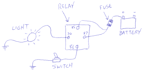
The AUX system excels at powering rugged exterior gear when installed with proper wire gauges and protection.
Power LED Rock Lights
Choose a 25A or 40A circuit based on your total light draw. Run 10-gauge marine-grade wire from Relay 1 to light locations using relay-controlled wiring. Seal all splices with adhesive heat shrink and mount lights in fender wells or bumper mounts.
Connect a Winch
Use Switch 1 and Relay 1 rated for 40A dedicated heavy loads. Run thick 4-gauge wire from the relay output to the winch contactor. Fuse at the source within 18 inches of the battery with a 200–300A fuse. Always use a dual-battery setup for winch operations to avoid voltage collapse.
Avoid Common Installation Mistakes
Even experienced users make errors that compromise safety and performance of their electrical systems.
Top Mistakes to Avoid
- Drilling into aluminum body panels causes galvanic corrosion.
- Using undersized wire leads to overheating and voltage drop.
- Skipping heat shrink allows moisture ingress and short circuits.
- Daisy-chaining grounds creates poor return paths.
- Ignoring the color code label results in wrong relay assignments.
- Tapping into random harnesses voids warranties and causes faults.
Maintain Long-Term Reliability
The F-350 endures extreme vibration, moisture, and temperature swings that demand durable wiring solutions.
Durability Best Practices
Seal all splices with adhesive-lined heat shrink to prevent moisture intrusion. Secure wiring paths every 12 to 18 inches with zip ties to prevent vibration damage. Double-check connections annually for corrosion or looseness. Replace relays if switching becomes sluggish or intermittent.
Frequently Asked Questions About AUX Switches in F-350
What is the maximum amperage for F-350 AUX switches?
Circuit ratings vary by switch, with 40A for Switch 1, 25A for Switch 2, and 20A for Switches 3 and 4. Switches 5 and 6 can be modified for key-off power but still adhere to their specific fuse ratings.
Can I run accessories when my F-350 engine is off?
Yes, by modifying the under-hood relay box to enable key-off power. This involves removing a specific 5-amp fuse and repositioning the target relay to bypass the ignition lockout.
How do I prevent battery drain with key-off accessories?
Install a dual-battery system with an isolator to power accessories from a secondary battery. This protects your primary starting battery from draining during extended accessory use.
Where should I ground my auxiliary wiring?
Use only factory ground points near the relay box or firewall. Never drill into aluminum body panels as this causes galvanic corrosion and structural damage.
What wire size do I need for F-350 rock lights?
Use 10-gauge marine-grade wire for most LED rock light installations. Ensure your total light draw does not exceed the circuit rating of the switch you select.
Key Takeaways for Using AUX Switches in F-350
Mastering how to use AUX switches in F-350 trucks transforms your vehicle into a versatile platform for custom electrical projects. Remember that these switches send low-current signals to under-hood relays, keeping heavy loads safely outside the cabin.
Always match your accessory amperage to the correct circuit rating and use factory ground points to avoid corrosion. Test every circuit thoroughly and consider a dual-battery system for any key-off applications to protect your starting power.


