If your F150 instrument cluster not working, you’re dealing with more than an inconvenience. The instrument cluster displays your speed, RPM, fuel level, engine temperature, and critical warning lights. When it fails, you lose essential vehicle information that keeps you safe on the road. Thousands of F-150 owners across model years have faced sudden blackouts, flickering gauges, erratic needle movement, or complete cluster failure. The root causes range from simple blown fuses to complex CAN bus communication errors and internal circuit board damage.
This guide walks you through every diagnostic step and repair option. You’ll learn how to test fuses, perform resets, check ground connections, diagnose communication faults, and determine whether to repair or replace the cluster. Whether you drive a 1995 F-150 or a 2021 PowerBoost hybrid, you’ll find model-specific solutions here.
Check Critical Fuses First

Blown fuses are the most common and easiest-to-fix cause of cluster failure. A single faulty fuse can cut power to the entire instrument panel, mimicking a total hardware failure.
Locate and Test Fuse F11 (Cabin)
The cabin fuse box sits under the driver side dashboard. Fuse F11 directly powers the instrument panel cluster in most 2004-2020 F-150 models. Use a fuse puller to remove it and inspect the filament. A broken filament means the fuse is blown. Test with a multimeter even if the fuse looks intact.
Critical Warning: Do not confuse cabin F11 with underhood F11, which controls power running boards. Always check the factory service manual for accurate fuse mapping.
Inspect Supporting Fuses F28 and F32
Fuses F28 and F32 in the cabin box support the Smart Junction Box or Body Control Module. These modules manage power distribution and communication to the cluster. If they fail, the IPC may lose signal or partial power. Test all three fuses even if only one appears damaged.
Older Models: Check Fuse Number 8 (1992-1996)
In pre-2004 F-150s, Fuse Number 8 controls the speedometer, odometer, dome light, and bed light. A blown fuse disables multiple systems at once. Replace it with the correct amperage, usually 15A. Repeated blowing indicates a short circuit somewhere in the wiring.
Test Battery and Charging System
Low voltage or a failing charging system can prevent the cluster from initializing properly, especially in modern F-150s with digital displays.
Measure Resting Battery Voltage
With the engine off, check battery voltage across the terminals using a multimeter. A healthy battery reads 12.6V. Anything below 12.4V may cause cluster memory loss, flickering, or failure to start the self-test sequence.
Verify Charging Output
Start the engine and recheck voltage. It should rise to 13.7-14.7V. If it stays low, the alternator is not charging properly, leading to unstable cluster behavior. Inspect alternator connections and belt tension.
Address Aftermarket LED Lighting Issues
Aftermarket LED bulbs can alter circuit resistance and trigger compatibility issues with the IPC. Some users report cluster resets or flickering after LED installations. Revert to OEM-spec bulbs if problems begin after an upgrade.
Perform a Hard Reset
A simple reset can resolve software glitches, memory corruption, or temporary communication errors, especially in 2015+ models with integrated infotainment systems.
Disconnect Battery for 10-30 Minutes
Turn off the truck, remove the key, and disconnect the negative battery terminal. Wait at least 10 minutes. Thirty minutes is better for stubborn issues. This allows all modules to fully power down and clears error states in the IPC, BCM, and SJB.
Advanced Reset: Discharge Residual Power
For persistent issues, disconnect both terminals and briefly touch them together to discharge remaining current. Reconnect, start the engine, and observe the cluster during startup.
Try Soft Reset on Modern Models
On 2015+ F-150s, turn the ignition to On without starting. Press and hold the trip reset button on the cluster. Wait 10-15 seconds for the gauges to sweep and reset. This can clear error screens or restore default display settings.
Diagnose Ground Connection Faults
Poor grounding is a hidden culprit behind intermittent cluster issues. It is often mistaken for wiring or module failure.
Locate Key Ground Points
The primary ground for the IPC, BCM, and GEM modules is typically near the driver footwell, close to the parking brake. Look for a metal strap bolted to the chassis with multiple wires attached.
Clean and Secure the Ground
Remove the bolt. Clean both the strap and contact point with sandpaper or a wire brush. Reattach tightly. Corrosion or looseness here disrupts both power and CAN signal integrity.
Test for Continuity
Use a multimeter to check continuity between the ground point and the negative battery terminal. Resistance should be near 0 ohms. Any reading above 1 ohm indicates a poor connection.
Scan for Diagnostic Trouble Codes
Use an OBD-II scanner to pull trouble codes, especially U-codes that reveal communication issues between modules.
Look for U0155: Lost Communication With IPC
This code confirms the PCM or BCM cannot talk to the instrument cluster. Causes include dead IPC, CAN bus interruption, power or ground failure, or internal cluster fault.
Check for Related Codes
U0140 indicates lost communication with PCM. B1868, B2097, and U2013 point to power or grounding issues at the cluster. C1234 suggests a CAN bus short or open circuit.
Note: Some codes require a Ford IDS scanner for full access, especially on 2015+ models. Generic OBD-II tools may not retrieve all available data.
Test CAN Bus Communication

The instrument cluster relies on the Controller Area Network to receive data from other modules. A broken network kills cluster function entirely.
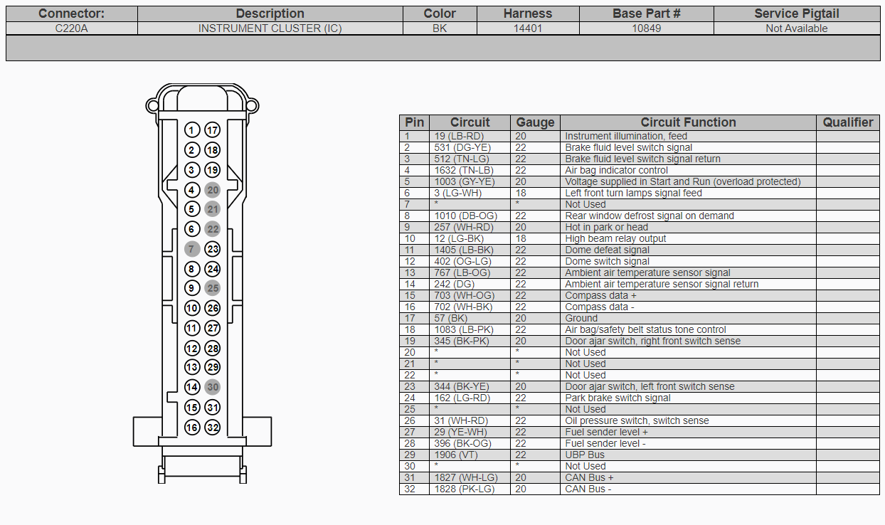
Measure CAN Bus Resistance
With the battery disconnected, locate the cluster connector and measure resistance between CAN High (Pin 6) and CAN Low (Pin 14). Expected reading is approximately 60 ohms due to termination resistors. Too high means an open circuit. Too low means a short or extra node. Zero ohms means a direct short.
Inspect Wiring for Damage
Check the harness from the cluster to the SJB for pinched wires, rodent damage, corrosion at connectors, and loose pins. Repair damaged sections with solder and heat shrink. Avoid butt connectors.
Examine the Smart Junction Box
The SJB acts as the central electrical brain, managing power and CAN communication to the cluster.
Recognize SJB Failure Signs
Multiple electrical systems failing simultaneously suggests SJB problems. This includes lights, wipers, and cluster. Persistent U0155 after cluster replacement also points to SJB issues. Intermittent power to IPC is another indicator.
Test or Replace SJB
If CAN bus and cluster are functional but communication fails, the SJB may be faulty. Swap in a known-good unit for testing. Some users report no improvement after SJB replacement, so confirm the diagnosis before buying a new unit.
Inspect Instrument Cluster Hardware
If power, ground, and communication check out, the issue likely lies inside the cluster itself.
Remove and Open the Cluster
Remove two Phillips screws from the rear cover. Release plastic clips and separate the housing. Mark needle positions with a pencil before removal. Gently lift needles off their shafts. Disconnect the PCB by releasing locking tabs.
Check for Cracked Stepper Motor Pins (2010-2014)
In 2010-2014 F-150s, cracked solder joints on stepper motor pins are the number one failure cause. Use a magnifier to inspect each gauge motor for speedo, tach, fuel, and temp. Gray versus white motor types are not interchangeable.
Resolder Faulty Joints
Use a pencil-tip soldering iron set to approximately 750°F with flux and thin lead-free solder. Heat each pin briefly. Apply fresh solder for a shiny, concave joint. Avoid bridging pins. Reassemble and test before final installation.
Replace Bulbs or LEDs
Older Models: Replace Incandescent Bulbs
Use wedge-base bulbs such as 168 or 194 for backlighting. Replace any that appear dark or dim.
Modern Models: LED Backlight Failure
LEDs are soldered to the PCB. If backlight is weak or dead, repair requires cluster disassembly and LED replacement or board-level fix. Full cluster replacement is another option.
Reprogram the Instrument Cluster
A cluster may lose settings or fail to initialize due to software corruption.
Use IDS With As-Built File
Retrieve as-built data from motorcraftservice.com/asbuilt using your VIN. Connect a Ford IDS scanner. Perform PMI (Programmable Module Installation). Select No when asked to retrieve data online. Load the downloaded file instead.
This restores unit preferences (MPH/KM/h), calibration, display configuration, and TPMS settings.
Model-Specific Fixes
1992-1996: Check Speed Sensor and Fuse Number 8
Test the rear axle speed sensor. Inspect the tone ring for rust or damage. Replace Fuse Number 8 if blown.
2004-2008: Ground and GEM Module
Clean the footwell ground. Replace the GEM module if it causes erratic lights and gauges.
2010-2014: Stepper Motor Repair
Solder cracked pins. Or send the cluster to Circuit Board Medics or UpFix for professional repair.
2021+ PowerBoost: 12V Battery and Water Damage
Test the under-seat auxiliary 12V battery, which is critical for hybrid models. Check the passenger footwell for water intrusion damaging the BCM. Perform a soft reset via infotainment if the cluster goes blank.
When to Repair Versus Replace
Choose repair when you see flickering and needle jitter on 2010-2014 models. This usually indicates stepper motor pin issues. Choose replacement when there is no power and no lights, but only after checking fuses, battery, and ground first. A cluster showing U0155 with good power requires CAN bus and SJB testing before replacement. Burnt PCB or swollen capacitors mean replace or professionally repair.
DIY repair costs under $50. Professional repair runs $150-300. New or rebuilt clusters cost $250-600.
Use Professional Repair Services
Circuit Board Medics
This service specializes in 2011-2014 F-150 clusters. They repair cracked pins, preserve mileage, and use donor units. Visit circuitboardmedics.com for more information.
UpFix
UpFix offers testing, repair, and warranty. They provide mail-in service. The address is 4991 BU Bowman Dr., Suite 100, Buford, GA 30518.
Prevent Future Cluster Failures
Replace the 12V battery every 3-5 years. Keep terminals clean and tight. Avoid deep discharges by not leaving accessories on. Fix leaks immediately to prevent water damage in the footwell. Clear AC drain lines to prevent moisture buildup. Use OEM-spec parts, especially for lighting upgrades.
Frequently Asked Questions About F150 Instrument Cluster Not Working
Why does my F150 cluster only light up briefly then go out?
This symptom typically points to a ground connection problem or failing IPC power supply. Check the ground strap near the driver footwell. Inspect Fuse F11 in the cabin fuse box. If the cluster lights up for about 3 seconds, it may be attempting to initialize but losing power.
Can I drive my F-150 with a non-working instrument cluster?
Driving without a functioning cluster is not recommended. You lose critical information including speed, fuel level, and warning lights. In many states, a non-functional speedometer may violate vehicle inspection requirements. Address the issue promptly for safety and legal compliance.
Why does my cluster reset to KM/h automatically?
This indicates cluster memory loss, usually caused by low battery voltage during shutdown or internal EEPROM failure. Reprogram the cluster using IDS with your as-built file. Replace the main 12V battery if it tests weak.
What causes the speedometer to jump around erratically?
Erratic speedometer movement often stems from cracked solder joints on the stepper motor in 2010-2014 models. A faulty vehicle speed sensor or damaged tone ring can also cause this. Check for diagnostic codes and inspect the rear axle speed sensor.
How much does it cost to fix a Ford F-150 instrument cluster?
DIY repair costs under $50 if you solder the stepper motor pins yourself. Professional repair runs $150-300. A new or remanufactured cluster costs $250-600 plus programming fees.
Is the instrument cluster covered under Ford warranty?
The instrument cluster is covered under the basic vehicle warranty, typically 3 years or 36,000 miles. Extended bumper-to-bumper warranties may also cover it. Aftermarket warranties vary. Check your coverage before paying out of pocket.
Key Takeaways for Fixing Your F150 Instrument Cluster
The F150 instrument cluster not working issue has multiple potential causes, but a systematic approach makes diagnosis manageable. Start with the simplest fixes: check F11 and related fuses, test battery voltage, and perform a hard reset. Move to ground connection inspection if the cluster shows partial operation or intermittent behavior. For 2010-2014 models, cracked stepper motor pins are the most common culprit and respond well to DIY soldering repair. Modern 2021+ models require attention to 12V battery health and water intrusion in the passenger footwell.
Use OBD-II scanning to identify communication codes like U0155. Test CAN bus resistance to rule out network faults. When in doubt, professional repair services like Circuit Board Medics offer cost-effective alternatives to full cluster replacement. Maintain your 12V battery, address electrical issues promptly, and use OEM parts to prevent future failures. With the right diagnosis, most cluster problems can be resolved without replacing the entire unit.