
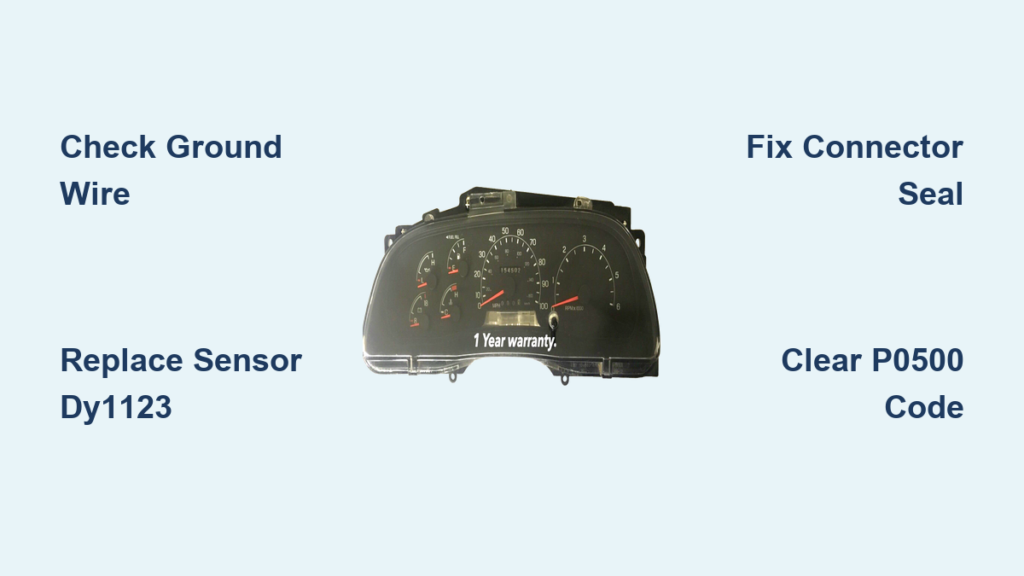
A dead speedometer on your 1999 F350 often triggers panic about a blown transmission, especially when the shifter light flashes. This common electrical glitch usually stems from a failed rear differential sensor or a loose ground wire rather than internal mechanical damage.
This guide walks you through diagnosing the exact cause, replacing the faulty Vehicle Speed Sensor, and securing connections to restore full function. You will learn how to fix this problem in under an hour using basic tools and avoid unnecessary repair costs.
Diagnose the Root Cause Before Replacing Parts

A non-functional speedometer paired with a flashing transmission light rarely indicates a broken transmission. The issue typically lies within the vehicle speed sensor circuit or the ABS communication network.
Check for P0500 and ABS Communication Errors
Connect an OBD2 scanner like the Autel MaxiCheck MX808 to read codes from both the PCM and ABS modules. A P0500 code confirms the Powertrain Control Module lacks speed data. If the scanner cannot communicate with the ABS module at all, the problem is likely a power or ground loss to that specific unit.
Identify Key Failure Symptoms
Look for these specific signs to confirm an electrical fault rather than mechanical failure:
- Speedometer reads zero with no prior warning
- Transmission fault light flashes on the gear shifter
- ABS warning light remains illuminated on the dashboard
- Operation is intermittent and works sometimes
- Transmission enters limp mode or shifts erratically
- Scan tool shows no communication with the ABS module
How the Speed Signal Path Works in Your Truck
Understanding data flow helps you avoid wasting money on the wrong parts. The 1999 F350 does not use a transmission output sensor for speed data.
Rear Differential to ABS Module Data Flow
The system relies on a Vehicle Speed Sensor mounted on the top center of the rear differential. This component reads the ring gear rotation and sends the signal directly to the ABS Control Module. The module then broadcasts this data via the CAN bus to the instrument cluster, PCM, cruise control, and overhead console.
Why a Bad Ground Mimics Transmission Failure
If the ABS module loses power or ground, it cannot broadcast speed data to any other system. This single point of failure kills the speedometer and confuses the transmission logic simultaneously. A loose green ground wire can create symptoms that look exactly like a catastrophic transmission breakdown.
Top Three Causes for Speedometer Failure
Identifying the specific failure point saves time and ensures you buy the correct replacement parts. Most issues fall into three distinct categories involving sensors or wiring.
1. Failed Rear Differential Speed Sensor
The Motorcraft DY1123 sensor is the primary culprit in most cases. Internal electronics fail due to moisture ingress, vibration damage, or thermal cycling after years of service. Even if the sensor looks perfect externally, it can fail internally and cause intermittent signal loss.
2. Loose or Corroded ABS Module Ground
A green ground wire connects the ABS module to the engine block. If this connection becomes loose or corroded, the entire module loses power. No power means no speed data, resulting in a dead speedometer and a P0500 code. This fix often costs nothing and takes only minutes to resolve.
3. Brittle Sensor Connector Housing
The electrical connector on the speed sensor suffers from heat and vibration exposure over time. Plastic retention tabs become brittle and snap when you attempt to unplug them. A loose connection breaks the signal even if the sensor itself is still functional.
Replace the Differential Speed Sensor Correctly
Replacing the sensor requires basic hand tools and careful handling of the fragile wiring harness. Follow these steps to ensure a lasting repair.
Gather Required Tools and Parts
You need a 13mm socket and ratchet, a flathead screwdriver, electrical tape, thread sealant, and an OBD2 scanner. Purchase a new Motorcraft DY1123 sensor, as aftermarket units often fail prematurely.
Step 1: Locate and Remove the Old Sensor
Park the truck on a slight incline or lift it for better access to the rear differential. Chock the wheels securely before working underneath. Find the sensor on the top center of the differential housing and remove the 13mm mounting bolt. Wiggle the sensor gently to extract it from the housing.
Step 2: Handle the Fragile Wiring Connector
Use a flathead screwdriver to gently pry up the retention tabs on the wiring connector. Do not force it, as the plastic tabs likely snap during removal. Inspect the pins for corrosion or damage before proceeding with the new part.
Step 3: Install the New Sensor and Sealant
Insert the new Motorcraft DY1123 sensor into the differential housing. Apply fresh thread sealant to the mounting bolt threads to prevent differential fluid leaks. Tighten the bolt hand-tight plus a quarter turn to avoid damaging the sensor housing.
Step 4: Secure the Harness Connection
Plug the wiring harness into the new sensor firmly. Wrap the connection tightly with six to seven layers of high-quality electrical tape. Extend the tape over both the plug and the wiring to create a moisture-proof seal that prevents future corrosion.
Step 5: Clear Codes and Test Drive
Connect your OBD2 scanner and clear the P0500 code from the PCM memory. Turn the key to the On position to verify the ABS light cycles normally. Start the engine and drive at 5 to 10 mph to confirm the speedometer reads accurately.
Fix the ABS Module Ground Wire Issue
Check the ground connection before replacing any parts, as this simple fix resolves many communication failures.
Locate the Green Ground Wire
Find the ABS module near the brake master cylinder. Trace the green insulated wire from the module to its grounding point on the engine block. This wire provides the essential return path for the module electrical system.
Clean and Reattach the Ground Terminal
Disconnect the wire and inspect the terminal for corrosion or paint buildup. Clean the contact point on the engine block down to bare metal using sandpaper. Reconnect the terminal and tighten the bolt firmly to ensure a solid electrical path.
Verify the Repair Was Successful
Do not assume the job is done until you have validated the fix under real-world driving conditions.
Confirm System Functionality
Ensure the speedometer reads accurately at all speeds without dropping out. Verify that both the ABS and transmission fault lights remain off during operation. Check that the P0500 code does not return after clearing it.
Perform Real-World Validation Tests
Drive the truck on city streets, highways, and rough roads to simulate various vibration levels. If you tow heavy loads, test the vehicle under load to ensure the signal remains stable. The transmission should shift smoothly without entering limp mode.
Prevent Future Speedometer Failures
Regular maintenance of the electrical connections extends the life of your repair and prevents recurrence.
Protect the Electrical Connector
Re-wrap the sensor connector with fresh electrical tape every six months during oil changes. Look for cracks, moisture, or looseness in the tape seal. Apply dielectric grease inside the connector if you ever need to unplug it again.
Inspect Ground Connections Annually
Check the ABS module ground wire yearly, especially if you drive in snowy or salty conditions. Clean and tighten the connection if you see any signs of corrosion. Monitor the area around the sensor bolt for fluid leaks that indicate sealant degradation.
Frequently Asked Questions About 1999 F350 Speedometer Issues
Why does my transmission light flash when the speedometer dies?
The transmission relies on speed data from the ABS module to determine shift points. When the speed sensor fails or the ABS module loses ground, the PCM receives no speed data and triggers limp mode with a flashing light as a safety measure.
Can I drive my truck with a P0500 code?
You can drive short distances, but the transmission may shift erratically or stay in second gear. Avoid towing or highway driving until you fix the issue, as the lack of speed data affects engine and transmission performance.
What is the correct part number for the rear speed sensor?
The OEM part number for the 1999 F350 rear differential speed sensor is DY1123. Using the genuine Motorcraft part ensures compatibility and longevity compared to cheaper aftermarket alternatives.
How do I know if the ABS module is bad or just the ground wire?
If your scan tool shows no communication with the ABS module, check the green ground wire first. A loose or corroded ground often causes total communication loss, mimicking a failed module.
Will resetting the code fix the problem permanently?
Clearing the P0500 code only resets the warning light temporarily. The speedometer will fail again unless you repair the underlying issue, such as replacing the sensor or fixing the ground connection.
Key Takeaways for Fixing Your 1999 F350 Speedometer
The 1999 F350 speedometer not working issue is almost always an electrical fault involving the rear differential speed sensor or the ABS module ground wire. Replacing the transmission is unnecessary and costly when the root cause is a simple sensor or wiring problem.
Start by checking the green ground wire on the ABS module, then replace the DY1123 sensor if the ground is secure. Secure the connector with electrical tape and clear the P0500 code to restore full functionality to your truck.


