
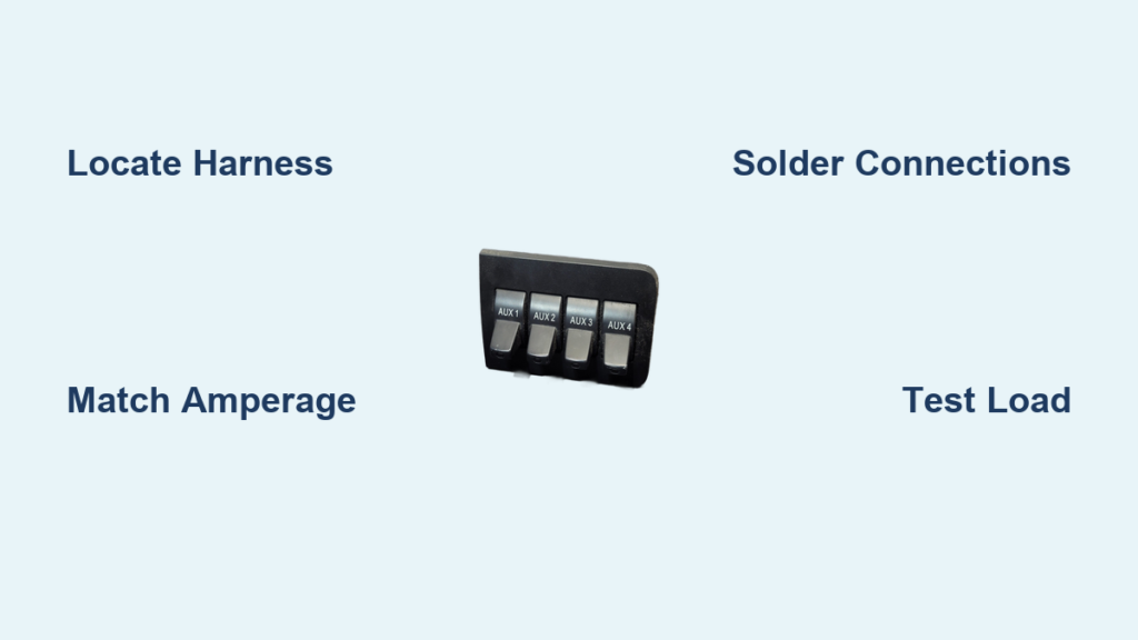
Powering aftermarket gear like LED bars or winches requires knowing how to hook up aux switches on F350 trucks correctly to avoid electrical failure. Ford’s factory upfitter system handles high loads safely through dedicated relays while keeping heavy wiring out of your cab.
This guide details exact wire locations for 2008 to 2024 models and explains safe splicing techniques. You will learn to match accessories to proper amperage ratings and modify circuits for key-off operation with confidence.
Locate Your F350 Upfitter Switch Harness

Finding the correct wires depends entirely on your truck’s model year since Ford changed the system architecture significantly. Older trucks use dead-ended bundles under the dash while newer models utilize an under-hood relay box.
2008–2016 Models: Under-Dash Bundle
These trucks feature four pre-routed wires located beneath the driver side dash below the steering column. The bundle is zip-tied and ends in bare tips waiting for your connection.
- Two switches provide 10A capacity for low load devices.
- Two switches offer 30A capacity for medium load tools.
- Common colors include White/Red and Gray/Orange stripes.
Pro Tip: Do not trust wire color alone. Use a multimeter to verify function by toggling each switch before cutting.
2017–Present Models: Under-Hood Relay Box
Newer Super Duties move the switching logic to a relay box on the passenger side firewall near the main fuse box. This design separates circuits clearly and simplifies access for engine bay accessories.
- Six labeled relays control individual switch functions.
- Switches 1 through 4 typically handle 20A to 25A loads.
- Switches 5 and 6 support up to 40A for winches or dual batteries.
Quick Check: Turn the key to On and flip Switch 1 to test the Green/Brown wire at Relay 1 for 12 volts.
Access the Firewall Pass-Through Wires
Routing power to the engine bay or dash electronics becomes much easier using Ford’s built-in pass-through bundles. These wires eliminate the need to drill holes through the firewall.
2008–2016: Firewall Convenience Harness
A secondary set of wires exits the main harness near the brake booster and runs into the cowl area. These correspond directly to the under-dash bundle found inside the cab.
- Colors include Gray and Brown/White stripes.
- Some configurations include a solid White wire.
- Use these to feed power without penetrating the firewall.
2017–Present: Dedicated Pass-Through Bundle
Modern trucks include a specific bundle behind the firewall designed for dash-mounted devices. You can access this by removing the driver side floor panel and weather stripping.
- Wire colors include White and Gray/Orange.
- Ideal for powering dash cameras or GPS units.
- Keeps your installation clean and factory-compliant.
Smart Move: Splice into these existing wires instead of running new cables to maintain a professional look.
Match Accessories to Correct Switches
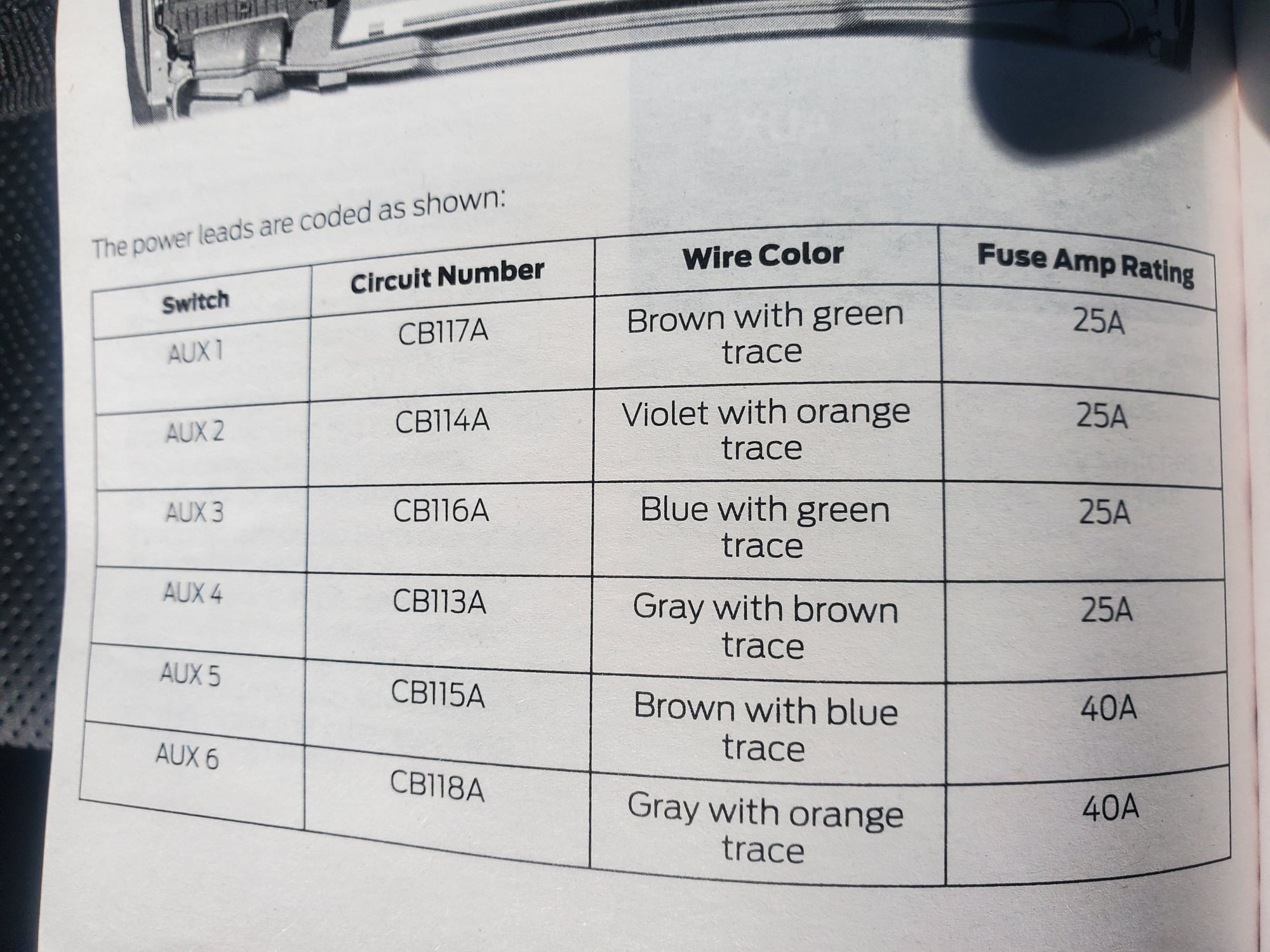
Connecting a device to the wrong circuit rating can blow fuses or damage your wiring harness. You must match the amperage draw of your accessory to the specific switch capabilities.
High-Load Devices: Use 30A–40A Circuits
Heavy equipment requires the highest rated switches to function safely without overheating. Always calculate 80 percent of the rated capacity as your maximum safe load.
- Best for winches and large LED light bars.
- Ideal for air compressors and auxiliary heaters.
- Use 30A switches on older models or Switches 5 and 6 on newer ones.
Rule of Thumb: A 30A circuit should never exceed a 24A continuous load to ensure safety margins.
Medium & Low-Load Devices: Use 10A–25A Circuits
Smaller electronics do not need high-current paths and should use lower-rated switches to preserve capacity for bigger tools. This prevents unnecessary strain on your primary circuits.
- Perfect for dash cameras and GPS units.
- Suitable for backup cameras and tire monitors.
- Use 10A switches on older trucks or Switches 1 through 4 on newer ones.
Pro Tip: Use a multi-outlet adapter to power several low-draw devices from a single low-amperage switch.
Make Reliable Electrical Connections
Vibration and moisture are the enemies of vehicle wiring so your connection method matters immensely. Poor connections lead to voltage drops and potential fire hazards in the engine bay.
Solder or Crimp: Choose the Right Method
You must choose a connection style that withstands the harsh environment of a working truck. Both soldering and quality crimping offer viable solutions if done correctly.
- Strip wire ends and twist them together tightly.
- Apply flux and solder until the joint is fully saturated.
- Slide heat shrink tubing over the joint and seal completely.
Best Practice: Soldered shrink tubing provides the most durable and waterproof result for long-term reliability.
Protect Connections from Vibration
Even a perfect solder joint can fail if it moves excessively within the engine bay. You must secure every connection against constant shaking and thermal cycling.
- Slide extra shrink tubing over the plastic sheathing before crimping.
- Wrap the entire connection with UL-listed electrical tape.
- Secure wires with zip ties every 6 to 8 inches along the route.
Pro Move: Route wires under the battery tray on diesel models for maximum protection and a clean appearance.
Ground Properly on Aluminum Bodies
Ford uses aluminum body panels on many F350 models which react poorly to improper grounding techniques. Creating new ground points by drilling can cause severe galvanic corrosion.
Never Drill Into the Frame
Drilling into the frame or body to create a ground spot invites rust and structural weakness over time. You must avoid penetrating the metal with new holes.
- Do not drill new holes for ground wires.
- Do not attach grounds directly to unpainted frame sections.
- Always use the existing factory ground screw locations.
Correct Grounding Procedure
The factory ground screw allows you to add your wire without compromising the vehicle structure. This method ensures a solid electrical path while preventing corrosion.
- Locate the factory ground screw near the firewall or relay box.
- Remove the screw completely from its mounting point.
- Place your new ground wire on top of the existing factory wire.
- Reinstall the screw tightly to ensure good contact.
- Use a Y-connector if grounding multiple components to one spot.
Diesel Tip: Route the ground wire under the passenger-side battery tray and secure it firmly with zip ties.
Modify for Key-Off Operation
Standard upfitter switches only receive power when the ignition key is in the On position. Some accessories like camp lights require power even when the truck is off.
Why Use Key-Off Power?
You need constant power for dual-battery systems or camping equipment that runs while the engine is off. The factory setup prevents this by default to protect the starter battery.
- Essential for refrigerator units and camp lighting.
- Required for auxiliary battery charging systems.
- Allows accessory use without running the engine.
How to Enable Key-Off Mode
You can modify specific high-amperage circuits to remain active regardless of ignition status. This involves a simple fuse swap in the under-hood relay box.
- Identify the circuit usually Switch 5 or 6 for this modification.
- Open the under-hood relay box and locate the high-amperage fuse.
- Remove the original fuse such as a 40A unit from the slot.
- Insert a 5-amp fuse in its place to activate the relay logic.
- The switch will now illuminate and function with the key off.
Warning: Only perform this on circuits designed for modification and consult your owner manual first.
Integrate Dashboard Devices
Centralizing control for all your dash electronics creates a cleaner cabin and easier operation. The upfitter system allows you to power multiple devices from a single switch location.
Centralize Control for Multiple Accessories
You can route power from the firewall bundle directly to your dash devices using the switch triggers. This keeps high-current wiring out of the passenger compartment.
- Identify control wires like Green/Brown for Relay 1.
- Splice these to the matching White/Orange wire in the firewall bundle.
- Fish wires up behind the center console using existing channels.
- Connect devices like dash cams to Socket 1 and GPS to Socket 2.
- Drill a small hole in the center console tray to feed wires cleanly.
- Reassemble the floor panel ensuring no wires are pinched.
Test: Flip Switch 1 to verify the dash cam powers on immediately.
Test and Verify Your Setup
Never assume your installation is correct without thorough testing under load. A proper verification process ensures safety and reliability before you hit the road.
Pre-Installation Checks
Verify every wire function before connecting your expensive accessories to the system. This step prevents accidental shorts or incorrect wiring configurations.
- Use a multimeter to confirm wire function before connecting loads.
- Verify 12V at the relay wire when the switch is activated.
- Take a photo of the relay box label before disconnecting anything.
Final Load Test
Connect a real load to the circuit to ensure it handles the demand without issues. Listen for the relay click and watch for consistent power delivery.
- Reconnect the relay box harness and secure with the 10mm nut.
- Attach the ground wire using the Y-connector method.
- Connect a test load like a heavy-duty LED bar to the circuit.
- Flip the switch and listen for the relay click and light activation.
- Cycle the switch multiple times to check for intermittent issues.
Pattern Test: If using strobe patterns ensure the switch handles rapid cycling without overheating.
Follow Critical Safety Practices
Electrical work on a vehicle carries risks of fire or damage if safety protocols are ignored. Always prioritize personal safety and vehicle integrity during installation.
Always Disconnect Battery First
Removing power sources prevents accidental shorts while you work near live circuits. This is especially critical when working near the main fuse box.
- Remove the negative terminal before working near the fuse box.
- Cover positive terminals with a thick rubber glove if both batteries are removed.
- Ensure no metal tools touch exposed battery posts.
Use Correct Fuse Ratings
Using the wrong fuse size can lead to melted wires or electrical fires in your truck. Always match the fuse to the specific switch rating and load requirements.
| Switch Rating | Max Fuse | Safe Load |
|---|---|---|
| 10A | 10A | 8A or less |
| 20A | 20A | 16A or less |
| 30A | 30A | 24A or less |
| 40A | 40A | 32A or less |
Critical: Never use a higher-rated fuse than specified as this risks fire or wiring damage.
Frequently Asked Questions About F350 Aux Switches
Can I use upfitter switches for key-off accessories?
Yes you can modify Switches 5 and 6 for key-off operation by replacing the main fuse with a 5-amp fuse. This allows the relay to engage and power accessories even when the ignition is off.
Where are the aux switch wires located on a 2015 F350?
On 2008 to 2016 models the wires are found beneath the driver side dash below the steering column. They appear as a zip-tied bundle of four dead-ended wires with bare tips.
What happens if I exceed the amperage rating on a switch?
Exceeding the rating will blow the fuse protecting that circuit or potentially melt the wiring harness. Always calculate 80 percent of the rated capacity as your maximum continuous load.
Do I need to drill holes to install upfitter switches?
No drilling is required because Ford provides pass-through bundles and pre-routed wires for most installations. Drilling into aluminum bodies can cause galvanic corrosion and should be avoided.
How do I identify which wire controls which switch?
Use a multimeter to test for 12 volts while toggling each switch in the cab. Wire colors can vary by model year so verification with a meter is the only reliable method.
Key Takeaways for Hooking Up Aux Switches on F350
Mastering how to hook up aux switches on F350 trucks unlocks powerful customization options for your work rig or adventure vehicle. Always match your accessory load to the correct switch rating and use proper soldering or crimping techniques for lasting results.
Remember to ground exclusively to factory points on aluminum bodies and disconnect batteries before starting work. Test every circuit with a multimeter and a real load before finalizing your installation to ensure safety and reliability.


