

If your F-150 odometer not working, you’re not alone. This is a widespread, well-documented issue affecting Ford F-150 trucks, especially models from 1997 to 2008, though problems persist into newer years. The most common symptom is a dark or flickering digital odometer that makes reading your mileage impossible. Often, it’s not just the odometer. Speedometer failure, cruise control issues, and warning lights like the wrench indicator may appear too.
The root cause is usually cracked solder joints on the instrument cluster’s circuit board. Vibration and heat over time break electrical connections, cutting power to the display. But other culprits like blown fuses, faulty speed sensors, or PATS system errors can mimic or worsen the problem. The good news: most cases can be fixed for under $30 with basic tools and a soldering iron. This guide walks you through diagnosis, repair, replacement, and programming so you can restore your F-150 dash for good.
Confirm Odometer Failure Type
Before tearing into your dash, identify what is really broken. This saves time and prevents unnecessary parts purchases.
Is It Illumination or Data Loss
Check these signs to determine the exact problem:
- Backlight off but numbers visible in daylight points to a bulb or power issue
- No numbers at all indicates PCB or communication failure
- Flickers when you tap the dash is a classic sign of loose solder joint
- Works briefly after restart suggests an intermittent connection
Check Related Functions
Test these systems to narrow down the cause:
- Can cruise control engage? If yes, speed data is likely reaching the PCM
- Is the wrench light on? This indicates powertrain or cluster communication fault
- Engine hesitating? May point to VSS or PCM issues, not directly odometer-related
Pro Tip: Use your phone flashlight and shine it on the odometer. If you see faint digits, the LCD is alive but unlit.
Test Fuses First
Blown fuses are the easiest fix and are often overlooked during diagnosis. Always check these first before moving to more complex repairs.
Locate and Inspect Key Fuses
These three fuses are critical for instrument cluster operation:
- Fuse #2 supplies instrument cluster power
- Fuse #5 controls cluster lighting
- Fuse #29 handles communications module
Steps to test fuses:
- Open the fuse box on the driver side dash or under the hood
- Pull each fuse using a tester or multimeter set to continuity
- Look for broken filament or corrosion on the metal strips
- Replace with the same amp fuse, typically 10A or 15A
Warning: If a fuse is blown, do not just replace it. Find the short circuit first. Repeated blowouts mean there is wiring damage somewhere in the system.
Diagnose Wiring and Connectors
Damaged harnesses cause intermittent cluster behavior and can mimic odometer failure. Inspect these areas carefully.
Inspect the Steering Column Harness
Follow these steps to examine the wiring:
- Remove the lower dash panel using a trim removal tool
- Look for chafed, pinched, or corroded wires behind the cluster
- Check where the harness routes near metal brackets
- Wrap any exposed sections with electrical tape or split loom tubing
User BobVanceFridge reported wires rubbing against metal, causing intermittent failures. Inspect this area carefully.
Check Cluster Connectors
Two main plugs attach to the back of the cluster:
- White connector carries power and data signals
- Black connector handles ground and lighting circuits
Action steps:
- Disconnect both connectors by pressing the release tabs
- Inspect for bent pins, moisture, or white-green crust (corrosion)
- Clean with electrical contact cleaner
- Reconnect firmly until you hear the click
Visual Cue: Green or white crust on terminals means corrosion. Clean with isopropyl alcohol before reconnecting.
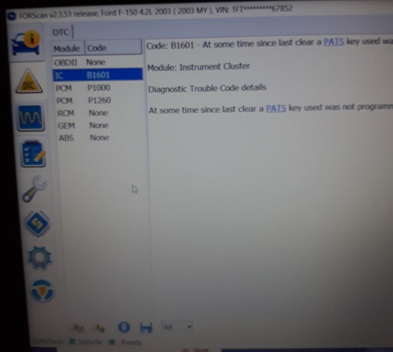
Use OBD-II Scanner for Error Codes
A scan tool reveals hidden electrical faults that are not visible during physical inspection. This step is crucial for accurate diagnosis.
Key Codes to Watch For
Watch for these specific diagnostic trouble codes:
- P0500 indicates Vehicle Speed Sensor (VSS) failure
- U0121 means lost communication with instrument cluster
- P1260 shows PATS system malfunction
- B1601 signals instrument cluster circuit fault
Real-Time VSS Testing
Use ForScan, IDS, or a compatible OBD-II app to monitor sensor data:
- Connect the scanner to the OBD-II port
- Monitor VSS output voltage while someone drives the vehicle
- Zero volts indicates a bad sensor or wiring problem
- Fluctuating signal suggests an intermittent connection
Critical Insight: If the speedometer works but the odometer is dark, the VSS is likely fine. The problem exists in the cluster display circuit itself.
Identify Cracked Solder Joints (1997-2008)

This is the number one cause in 9th and 10th generation F-150s. The problem is well-documented and repeatable to fix.
Locate the Failure Zone
Remove the instrument cluster and flip the circuit board over:
- Find the notched cutout on the lower-left corner of the PCB
- Examine the two solder points on either side of the notch
- These are the most common failure points in affected models
Why They Crack
Three factors cause these joints to fail:
- Vibration from driving fatigues the solder over years
- Thermal cycling expands and contracts the metal repeatedly
- Factory lead-free solder is brittle and prone to cracking
User Report: Ashton Marshall reported that resoldering one joint failed within weeks. You must fix both sides of the notch for lasting results.
Remove Instrument Cluster
Follow these steps carefully to avoid damaging the dash or connectors.
Tools Needed
Gather these tools before starting:
- 7 mm socket or 9/32 inch nut driver
- Torx T15 screwdriver
- Trim removal tool
- Flat pry bar
Step-by-Step Removal (1997-2008)
-
Remove dash trim. For 2001-2003 models, turn headlamp switch on, pull out, rotate 180 degrees, reinsert, then turn off to release the assembly. Remove upper trim bolts (9/32 inch) and unfasten lower left and right trim screws.
-
Disconnect wiring by unplugging white and black harnesses (press tabs). Disconnect adjustable pedal module if equipped, then unplug headlamp switch.
-
Unbolt the cluster by removing the four 7 mm bolts. Gently pry forward with the trim tool. Slide out while clearing the gear shift indicator.
Pro Tip: Label each connector before disconnecting. This saves significant time during reassembly.
Repair Solder Joints
This is the core repair that fixes most F-150 odometer not working issues. Take your time and work carefully.
Tools and Materials
| Item | Purpose |
|---|---|
| 600-700°F temperature-controlled soldering iron | Controlled heat application |
| 60/40 tin-lead rosin-core solder | Flexible, durable bond |
| Desoldering wick | Clean up bridges and excess |
| Magnifying glass | Spot hairline cracks |
| Multimeter | Test continuity |
Repair Steps
-
Open the cluster housing by removing seven Torx T15 screws from the back. Flip the PCB carefully, avoiding force on ribbon cables.
-
Locate and resolder the joints. Focus on both sides of the lower-left notch. Heat each pad and apply fresh solder. Use the desoldering wick to avoid bridging adjacent pads.
-
Test continuity by setting the multimeter to continuity mode. Probe both sides of each joint. A beep means good connection.
Warning: Never touch solder near the PATS module unless you have experience. A bridge can brick the cluster and prevent the engine from starting.
Reassemble and Reinstall
Follow this checklist to ensure proper reinstallation.
Reassembly Checklist
- Reconnect the two ribbon cables, depressing tabs fully
- Replace the back cover and seven T15 screws
- Slide cluster into the dash, aligning the gear indicator with the shifter
- Press side tabs to lock the gear lever in place
- Reconnect all harnesses: white, black, pedal, and headlamp
- Secure with four 7 mm bolts
- Reinstall trim panels and all fasteners
Pro Tip: Before powering up, double-check that all connectors are fully seated.
Test After Repair
Turn the ignition to ON but do not start the engine yet.
What to Verify
Check these functions before driving:
- Odometer illuminates and stays on without flickering
- Speedometer needle sweeps properly
- Trip meter resets when pressed
- Cruise control light turns on
- No wrench or theft warning light appears
Then start the engine and verify:
- No hesitation or stalling during startup
- Cruise control engages at 45+ mph
- No flickering under vibration while driving
Success: If all functions work for 10+ minutes, the repair is stable.
Replace Cluster If Repair Fails
Sometimes soldering is not enough. Know when to replace the entire unit.
When to Replace
Consider replacement if:
- Solder joints crack again after multiple repair attempts
- PATS circuit is damaged during repair
- Multiple gauges are dead or erratic
- Internal PCB traces are burned or damaged
Sourcing Options
| Option | Cost | Notes |
|---|---|---|
| Used cluster (eBay/junkyard) | $100-$300 | Check compatibility carefully |
| Remanufactured | $150-$250 | Often pre-programmed |
| New OEM | $300-$600 | Rare for older models |
| Dealer replacement | $500+ | Includes labor and programming |
Best Value: Remanufactured clusters with warranty offer the best balance of cost and reliability.
Program PATS and Mileage
This step is critical. Improper programming can prevent your F-150 from starting.
Why It Matters
PATS (Passive Anti-Theft System) is built into the instrument cluster on 1998 and newer models. Wrong programming means the engine cranks but will not start. The PCM stores true mileage, which must transfer to the new cluster during programming.
Requirements
You need two programmed keys to initialize PATS with a new cluster. If you only have one key, get a second cut by a locksmith for $50-$100.
Programming Methods
-
ForScan with OBD-II adapter (DIY). Free software works on Windows. Requires knowledge of module flashing. User Rebeldesuave reports any mechanic with ForScan can do it, not just dealers.
-
Dealer or specialty shop using IDS (Integrated Diagnostic System). Uses Ford’s official software. Reliable but costs $100-$300.
Case Study: User 1simplythebest1 found that after programming, the odometer showed lower mileage. The shop could not update it. Keep written documentation of the original mileage.
Handle Mileage Discrepancies
If the new cluster shows wrong mileage, take these steps.
What to Do
Ask the programming shop for a written statement explaining the discrepancy. Include the old mileage, reason for replacement, and the new cluster’s initial reading.
Legal Protection
This documentation is required for DMV registration and title transfer. In many states, vehicles over 10-15 years old are exempt from federal odometer reporting requirements.
Pro Tip: Keep the original cluster as proof of true mileage if you plan to sell the vehicle.
Prevent Future Failures
DIY repairs can fail over time. Reinforce your work for longevity.
Reinforcement Tips
Apply these upgrades after successful repair:
- Use conformal coating over solder joints to seal against vibration and moisture
- Add non-conductive foam between PCB and housing to dampen vibration
- Replace corroded connectors with new ones
Best Practices
Follow these rules during any electronics work:
- Work on an anti-static mat to prevent ESD damage
- Use a temperature-controlled iron to prevent overheating
- Never rush the repair. PATS damage is expensive to fix.
Cost Comparison: Repair vs Replace
| Option | Cost | Longevity |
|---|---|---|
| DIY solder fix | $10-$30 | Months to years with reinforcement |
| Professional repair | $150 | Dick Industries Inc (USA) |
| Used cluster + programming | $250-$400 | Reliable if PATS done correctly |
| Dealer replacement | $600+ | Full warranty but costly |
Bottom Line: DIY repair saves $500 or more, worth the effort for most owners.
Final Action Plan
Use this step-by-step guide to fix your F-150 odometer not working issue.
Step-by-Step Fix
- Check fuses #2, #5, #29 and replace if blown
- Inspect wiring for chafing or corrosion
- Scan for codes using ForScan to rule out VSS or PATS issues
- Perform a battery reset by disconnecting the negative terminal for 10 minutes
- Try the PATS reset with an 8-key cycle if the theft light is flashing
- Remove the instrument cluster following the disassembly steps
- Resolder both joints near the lower-left notch
- Test thoroughly, verifying all functions remain stable
- Replace with a remanufactured cluster if needed
- Program PATS using two keys and ForScan or a professional shop
Frequently Asked Questions About F-150 Odometer Not Working
What causes the F-150 odometer to stop working?
The most common cause is cracked solder joints on the instrument cluster circuit board, particularly in 1997-2008 models. These joints fail due to vibration and thermal cycling over time. Other causes include blown fuses, wiring harness damage, VSS sensor failure, and PATS system issues.
Can I drive my F-150 with a broken odometer?
Yes, you can drive, but it creates problems. You will not know your actual mileage for maintenance scheduling. Resale value decreases without documentation. Insurance claims may be affected. You cannot legally sell the vehicle without disclosing the actual mileage.
How much does it cost to fix an F-150 odometer?
DIY repair costs $10-$30 for tools and solder. Professional cluster repair runs about $150. Used cluster replacement with programming costs $250-$400. Dealer replacement runs $600 or more.
Do I need to reprogram the cluster after replacing it?
Yes, PATS programming is required for 1998 and newer models. You need two programmed keys. The PCM stores actual mileage, which transfers to the new cluster during programming. Without proper programming, the engine will crank but not start.
Why does my odometer flicker but still work sometimes?
Flickering indicates an intermittent connection, usually from cracked solder joints. Tapping the dashboard may temporarily restore function. This is a sure sign the solder joints need resoldering.
Can I fix the odometer myself with basic tools?
Yes, the repair is straightforward for those with moderate DIY skills. You need a soldering iron, multimeter, and basic hand tools. The hardest part is removing the instrument cluster without breaking clips. Take photos during disassembly to help with reassembly.
Key Takeaways for Fixing Your F-150 Odometer
The F-150 odometer not working issue is predominantly caused by cracked solder joints in the instrument cluster PCB, especially in 1997-2008 models. The repair is technically feasible for DIYers with proper tools and caution. However, the integration of PATS and mileage storage in the PCM adds complexity. Improper handling can prevent engine start, so work carefully around the PATS module.
For 2009-2014 models, diagnosis should prioritize VSS and communication faults using scan tools. In all cases, professional repair or replacement may be more reliable for users without electronics experience. This issue, while frustrating, is largely repairable without replacement, offering significant cost savings.
Due to reports of recurrence, reinforcement of repaired joints and careful PATS management are essential for long-term reliability. Apply conformal coating after repair, work on anti-static equipment, and document all mileage discrepancies for legal protection. With careful soldering and proper testing, you can restore full dash function for a fraction of dealer prices.


