

If your 2009 F-150 tachometer is not working, you are dealing with a frustrating but solvable problem. This issue affects thousands of F-150 owners, with symptoms ranging from a dead needle stuck at 0 RPM to erratic jumping or intermittent operation. The frustrating part is that there is often no Check Engine Light, making it harder to diagnose with basic tools.
The tachometer relies on a signal chain: the Crankshaft Position Sensor sends data to the Powertrain Control Module, which broadcasts RPM information to the Instrument Panel Cluster, where a tiny stepper motor moves the needle. A failure anywhere in this chain breaks the display. The good news is you can isolate and fix the root cause without replacing the entire dash.
In this guide, you will learn how to diagnose the exact failure point using free tools like Forscan, perform a gauge sweep test, access hidden test mode, and repair the most common culprit: the instrument cluster.
Start with a Gauge Sweep Test
Every tachometer diagnosis should begin with a gauge sweep test. This quick check takes seconds and reveals a lot about your cluster health.
Performing the Sweep Test
Turn the ignition to ON (do not start the engine) and watch all gauges including the speedometer, fuel, temperature, and tachometer. All needles should rise to maximum and then fall to zero.
If the tach needle does not move at all, this points to internal cluster failure, likely a dead stepper motor or power issue. If the needle sticks mid-sweep, this suggests mechanical binding or a calibration error.
Interpreting Sweep Results
No movement means the stepper motor is dead or the cluster is not receiving power. Partial movement indicates binding, a weak motor, or bad calibration. Full sweep but no RPM while running means the signal is lost after startup, so check the IPC or CAN bus.
Read DTCs with Forscan

Do not assume no Check Engine Light means no codes. Pending or stored DTCs can reveal hidden faults that generic scanners miss.
Using Forscan for Deep Diagnostics
Download Forscan (free Windows software) and use an ELM327 or Forscan-branded OBD-II adapter. Connect to the port under the dash and launch the software. Scan the PCM, IPC, and ABS modules for codes.
Key Codes to Watch For
P0335 indicates CKP Circuit Malfunction, pointing to the crank sensor or wiring. P0336 means CKP Range or Performance, suggesting a weak or erratic signal. U0100 indicates Lost Communication with PCM, which is a CAN bus or PCM issue. U2100 means Lost Communication with Cluster, an IPC communication failure. B2292 confirms Instrument Cluster Internal fault, indicating hardware failure. Code 212 indicates an IDM Failure, a TFI module problem.
If you find P0335 or P0336, test or replace the crankshaft position sensor. For U0100 or U2100, check the CAN bus wiring or suspect the PCM or IPC. B2292 confirms internal cluster failure, so tear it down and inspect. Code 212 means investigate the TFI module, which is common in older models.
Check Live RPM Data

Your PCM knows the engine speed even if your tachometer does not display it. This test alone can save you from replacing the wrong part.
Monitoring Real-Time RPM
In Forscan, go to Live Data and select Engine RPM. Start the truck and observe the digital reading. Rev the engine slightly and watch the RPM increase smoothly.
Interpreting the Results
If the digital RPM is normal (for example, 750 at idle) but the tachometer shows 0 or is stuck, the fault is in the IPC or gauge. If both digital and tachometer readings are erratic or missing, the problem is upstream at the CKP, wiring, or PCM. If the tach matches but is offset (for example, always 500 low), the needle is misaligned and needs calibration.
The key insight is this: if digital RPM is correct, the CKP, PCM, and CAN bus are working. The fault is entirely in the instrument cluster.
Activate Cluster Test Mode
This built-in feature bypasses the tachometer display and shows real RPM, perfect for diagnosis and temporary use while you plan repairs.
Entering Test Mode
Press and hold the trip reset button on the cluster. While holding, crank the engine. Keep holding until the display shows Test. Release the button.
Navigating to RPM Screen
Tap the reset button to cycle through screens. Stop when you see the RPM value, usually 750 to 1,000 at idle. Rev the engine and watch the number rise in real time.
Using It While Driving
The vehicle operates normally while in test mode. RPM data stays visible on the display. There are no safety risks. The mode resets when you turn off the ignition.
This matters because it confirms the CKP to PCM to IPC signal chain is intact and isolates the fault to the stepper motor or needle mechanism. If RPM updates in test mode, skip CKP and wiring checks and focus on the cluster.
Test the Crankshaft Position Sensor
The CKP sensor is the source of RPM data. If it fails, nothing downstream works properly.
Locating the Sensor
On 4.6L and 5.4L engines, the CKP sensor is mounted near the crankshaft pulley at the front of the engine. Look for a two-wire connector near the harmonic balancer.
Checking for Power and Signal
Disconnect the CKP connector. Set a multimeter to AC voltage. Crank the engine and measure across the terminals. Expect 0.5 to 5V AC fluctuating signal.
No signal means the sensor is dead or the wiring is broken.
Inspecting for Damage
Look for cracks, oil saturation, or impact damage. Check the air gap between the sensor tip and reluctor wheel, which should be about 0.5 to 1.5 mm. Ensure the wiring is secure and not chafed.
Replacing If Faulty
Use an OEM part recommended. Aftermarket sensors fail faster. Torque to spec, usually 8 to 10 ft-lbs. Route the harness away from hot or moving parts.
A bad CKP can cause hard starts, misfires, or no-start conditions. Do not ignore it.
Inspect Wiring and Connectors
A broken wire or corroded connector can kill the tach signal even if all modules are functioning correctly.
Focus on the White-Pink Wire
This wire carries the tach signal from the ignition suppression resistor to the cluster. Trace it from the PCM to the IPC connector C204 or C205. Check for cuts, pinches, or rodent damage.
Testing for Continuity
Disconnect the battery. Unplug both ends of the circuit. Use a multimeter in continuity mode. Probe along the white-pink wire. A beep means good continuity. No beep means a break in the wire.
Check Key Connectors
Inspect the CKP plug at the front engine for corrosion and bent pins. Check the PCM harness at the firewall for loose terminals. Examine the IPC C204 and C205 at the back of the cluster for burnt pins and poor contact. Verify ground points in the dash and engine are clean and tight.
Apply dielectric grease after repair to prevent moisture damage.
Diagnose the Instrument Cluster
Over 70% of 2009 F-150 tach failures trace back to the IPC, especially the stepper motor and solder joint issues.
Remove the Cluster
You will need a T15 Torx screwdriver, a plastic pry tool, and a small container for screws. First, disconnect the battery. Remove two front and one rear T15 screws. Gently pry the lens from the housing using fingers or a plastic tool. Remove the bezel and four bottom screws. Pull the cluster out and unplug C204 and C205.
Label connectors if unsure and take photos before disconnecting.
Repair the Stepper Motor
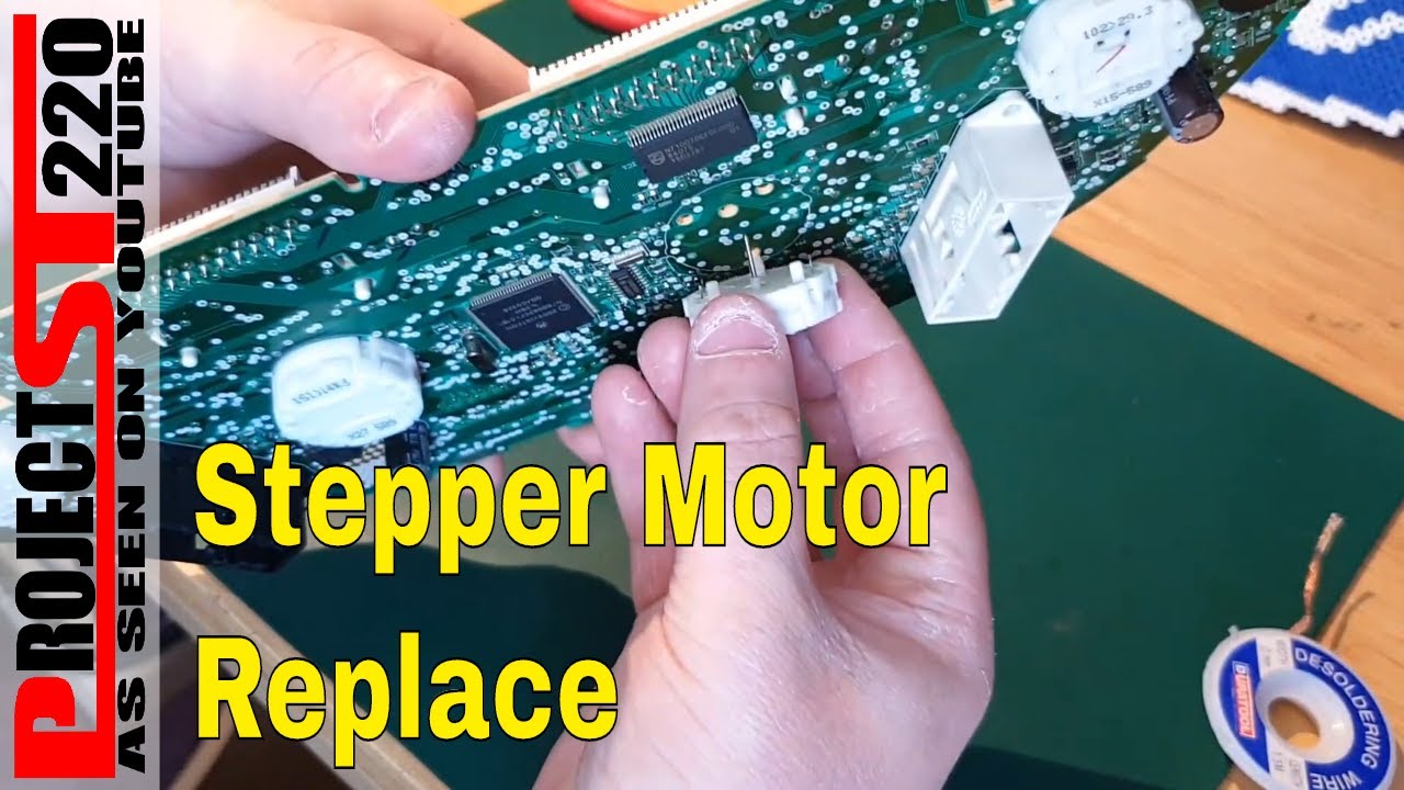
The tach needle is driven by a tiny stepper motor. When it burns out, the needle dies.
Identify the Right Motor
Gray stepper motors are the correct type. They are slightly longer and seat fully in the housing. White stepper motors are shorter. Do not use them as replacements because they cause misalignment and premature failure.
Replace or Rebuild
Option one is to transplant from a donor cluster. Source a working cluster for $50 to $100 online. Desolder the gray motor and swap it into your cluster.
Option two is to buy a replacement motor. Search for 2009 F-150 tach stepper motor gray and solder it in carefully. Do not overheat the PCB.
Fix Cracked Solder Joints
Vibration and heat cause cracks in solder joints, especially on the power ring around the main connector.
Inspect Under Magnification
Open the cluster housing. Shine a bright light on the circuit board. Look for visible gaps in the solder around large copper rings.
Re-Flow the Joints
Heat the joint with a soldering iron. Add heavy-gauge solder to bridge cracks. Ensure full wetting of the pad and pin. Clean with isopropyl alcohol to remove flux.
A success sign is the cluster powers up consistently after repair. A cold joint looks dull and bumpy. Reheat it until shiny and smooth.
Calibrate the Tachometer Needle
After repair, the needle may sit at the wrong position.
Set Needle at Rest
Before final assembly, manually position the tach needle one needle width below zero. Do the same for speedo, oil pressure, and temp gauges. For the fuel gauge, position it one and a half needle widths below zero.
Perform Final Gauge Sweep
Reinstall the cluster. Reconnect the battery. Turn the key to ON. Watch all needles sweep fully and smoothly.
If the tach moves but stops short, reposition the needle and retry.
Check the TFI Module
On some 2009 models, the Thick Film Ignition module supplies the tach signal.
Diagnose with Code 212
Use Forscan to check for IDM Failure (Code 212). No CEL does not rule it out. Scan anyway.
Replace If Needed
The TFI module is located near the distributor or ignition coil, varying by engine. Swap with an OEM unit if the code persists and other causes are ruled out.
This is less common than IPC failure, but test it if everything else checks out.
Repair Cost Comparison
CKP sensor replacement costs $50 to $100 DIY or $150 to $300 at a shop. Wiring repair costs $20 to $50 DIY or $100 to $200 at a shop. Solder joint fix costs under $20 DIY or $200 to $400 at a shop. Stepper motor swap costs $30 to $80 DIY or $300 to $500 at a shop. A refurbished cluster costs $400 to $800 DIY or $600 to $900 at a shop. TFI module replacement costs $80 to $150 DIY or $200 to $300 at a shop.
DIY cluster repair saves $300 or more and teaches valuable skills.
Professional Repair Services
Atlanta Speedometer specializes in F-150 clusters. They repair stepper motors, fix solder joints, and calibrate gauges. They also program refurbished clusters to your VIN.
Their address is 590 North Price Rd, Suite B, Sugar Hill, GA 30518. Call them at 770-831-8802. They are open Monday through Friday, 9 AM to 5 PM EST.
Prevent Future Failures
Apply dielectric grease to all connectors. Fix vacuum leaks promptly to prevent engine stress. Avoid off-road impacts because the CKP sensor is vulnerable. Clean cluster contacts during major service.
Monitor early signs. Slow gauge sweep means the stepper motor is weakening. Intermittent tach means cracked solder or loose plug. Flickering lights mean a power supply issue.
Catch it early and fix it fast.
Final Test After Repair
Do not assume it is fixed until you verify.
Step-by-Step Verification
Reinstall the cluster and secure all screws. Reconnect the battery. Turn the key to ON and perform the gauge sweep. Start the engine and watch the tach respond to revs. Use Forscan to confirm no new DTCs. Test drive and check for intermittent dropouts.
Success means the needle moves smoothly, matches engine speed, and there are no codes.
Frequently Asked Questions About 2009 F-150 Tachometer Not Working
Why does my 2009 F-150 tachometer show 0 RPM even when the engine is running?
This typically indicates a problem in the instrument cluster, specifically a failed stepper motor or cracked solder joint. The CKP sensor and PCM are usually working fine if the engine runs normally. Use Forscan to check live RPM data. If the digital reading is correct, the fault is in the IPC.
Can I drive my 2009 F-150 with a broken tachometer?
Yes, you can drive without a working tachometer. However, use the built-in test mode to monitor RPM while driving. This displays the actual engine speed as a number rather than a needle. Just do not rely on the broken gauge for shift points or engine monitoring.
How much does it cost to fix a 2009 F-150 tachometer?
DIY costs range from $20 for a solder repair to $80 for a stepper motor. Professional shop repairs range from $200 to $500 for cluster work. A refurbished and programmed cluster runs $400 to $800 including parts and labor.
Do I need to reprogram the cluster after replacing the stepper motor?
No, the cluster does not need reprogramming for stepper motor or solder repairs. You only need programming if you replace the entire cluster with a refurbished unit. In that case, the new cluster must be programmed to your VIN.
What is the gauge sweep test and why does it matter?
The gauge sweep test is when you turn the key to ON without starting the engine. All needles should rise to max and fall to zero. This tests the cluster power and stepper motor function. No movement during sweep confirms internal cluster failure.
Can a bad crankshaft position sensor cause tachometer failure?
Yes, absolutely. The CKP sensor is the source of the RPM signal. If it fails, the PCM receives no data to send to the cluster. Look for hard starting, misfires, or no-start along with tach failure. Test the CKP sensor with a multimeter for proper signal output.
Key Takeaways for Fixing Your 2009 F-150 Tachometer
The 2009 F-150 tachometer not working issue is rarely a mystery. With Forscan, a gauge sweep test, and test mode, you can pinpoint the cause in under an hour. Most fixes involve the instrument cluster, specifically the gray stepper motor or cracked solder joints on the power ring.
Start with the simplest diagnostics first. Perform the gauge sweep test to confirm cluster power. Use Forscan to read DTCs and monitor live RPM data. Activate test mode to verify the signal chain is intact. Only then should you remove the cluster for internal inspection.
Repair it yourself and save hundreds of dollars, or send it to a professional like Atlanta Speedometer. Either way, your tachometer can be fixed. No full dash replacement is needed.


