When your F350 parking lights and dash lights stop working simultaneously, it creates an immediate safety hazard and a frustrating diagnostic puzzle. This specific failure pattern often points to shared electrical faults rather than simple bulb burnouts, especially in 1999 through 2003 Super Duty models. Owners frequently report intermittent issues where lights flicker or fail completely without blowing fuses or triggering error codes.
This guide helps you diagnose the root cause of these lighting failures using proven troubleshooting methods. You will learn how to inspect the headlight switch, test the GEM module connections, and verify ground points to restore full functionality to your truck.
Identify Common Symptoms and Patterns
Recognizing the specific behavior of your lighting system helps narrow down the culprit quickly. When both exterior running lights and interior gauge illumination fail together, they share a common power source or control path that requires immediate attention.
Flickering or Intermittent Operation
Lights that flicker randomly or cut out when hitting bumps indicate a loose connection or corroded terminal. Since these issues often persist for months without triggering diagnostic codes, the problem is likely a physical electrical fault rather than a computer module failure.
Complete Failure in Both Circuits
A simultaneous loss of front parking lights, rear taillights, and dashboard backlighting suggests a shared power supply interruption. The instrument panel dimming circuit controls dash brightness and ties directly into the same feed as your exterior parking lights.
No Fuse Blows or Warning Lights
The absence of blown fuses rules out a hard short circuit in the system. This scenario typically points toward high resistance, poor grounding, or partial power loss that breaks the circuit without tripping standard safety protections.
Check the Headlight Switch First

The headlight switch on 1999 to 2003 F250 and F350 models is a known weak point for electrical failures. High mileage trucks or those with frequent light usage often suffer from internal contact wear within this component.
Why the Switch Fails
Internal contacts corrode or wear out over time, particularly affecting the lower-amperage parking light circuit. Your headlights may still function perfectly while the parking light distribution circuit fails independently due to this wear.
- Look for discoloration or melting around the switch plug connector.
- Wiggle the switch knob and stalk while observing lights for flickering.
- Use a multimeter to test for voltage drop across the switch output when activated.
Replace with OEM-Grade Part
Aftermarket switches often fail prematurely compared to original equipment. Opt for a Motorcraft or OEM-replacement unit to ensure longevity and proper fitment in your vehicle.
- Remove the two retaining screws located below the switch assembly.
- Unplug the electrical connector from the back of the switch.
- Install the new switch and test the system immediately.
Common Mistake: Assuming the switch is fine because the main headlights work. Always test the parking light circuit separately to confirm functionality.
Inspect the GEM Module Connections

The Generic Electronic Module (GEM) manages multiple body functions including lighting sequences on 1999 to 2003 Super Duties. This black control box sits behind the left-side kick panel near the driver’s footwell.
Locate the GEM Module
Remove the kick panel on the driver side to access the module. You will see a black box with multiple wire harnesses plugged into it that control various electrical functions.
Check for Moisture and Corrosion
Water intrusion from cowl areas or door seals can reach the GEM location easily. This moisture leads to corroded pins, intermittent signal loss, and the flickering dash and parking lights you are experiencing.
- Remove the kick panel and inspect the GEM housing for water stains.
- Unplug each connector and check terminals for green corrosion or white residue.
- Clean terminals with electrical contact cleaner and a small soft brush.
- Reconnect firmly and apply dielectric grease to prevent future corrosion.
Test Module Output
Use a test light or multimeter to verify power output from the GEM when parking lights are on. Probe the output wire, usually light blue or orange, to check for steady power. If power is missing, the GEM connectors may be failing internally.
Note: The GEM rarely fails completely. More often, the connectors themselves cause the issues rather than the module circuitry.
Trace the Park Lamp Relay Circuit

The park lamp relay supplies essential power to both exterior parking lights and the dash illumination circuit. A faulty relay can mimic a complete system failure even when other components are functional.
Find the Relay in the Fuse Box
Locate the under-hood fuse box on your truck. Look for the relay labeled “PARK LPS” or “PARK LIGHTS,” which is typically a 4-pin or 5-pin Bosch-style component.
Test Relay Function
Turn on the parking lights and listen for a faint click from the relay. If you hear no click, swap the suspect relay with a known-good one like the horn relay to test functionality.
Check Power at Relay Terminals
Use a test light to verify voltage at specific terminals while the system is active. Terminal 30 should have constant battery voltage, while terminals 85 and 86 receive the control signal from the GEM. Terminal 87 provides output to the lights and should be live when the relay is energized.
Examine Instrument Cluster Wiring Harness
The instrument cluster receives its backlighting from the same circuit that powers your parking lights. Damage here can cause dash lights to go out even if exterior lights remain functional.
Remove the Cluster for Inspection
Disconnect the battery before starting this process. Remove the trim bezel and two mounting screws, then gently pull the cluster forward to unplug the connectors.
Look for Damaged or Loose Wires
Focus your inspection on the gray connector, known as C235b, which carries dimming and illumination signals. Check thin-gauge wires that feed the gauge faces and warning lights for breaks or fraying.
Common Issue: Broken solder joints or cracked circuit board traces inside the cluster can cause dash lights to fail. This happens even if power is present at the main connector.
Test Backlighting Power
With parking lights on, backprobe the orange or violet wire for a 12V feed. Check the dark green or white wire for ground continuity to ensure the circuit is complete.
Diagnose Grounding Problems
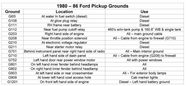
Poor grounding causes silent failures in older F350 trucks. The dash and parking lights rely on clean, solid ground paths to function correctly and consistently.
Identify Key Ground Points
Critical grounds for lighting circuits include G100 at the left kick panel and G200 at the right kick panel. Check G301 under the dash near the steering column and G501 at the front radiator support.
Clean and Reconnect Ground Straps
Remove each ground bolt and sand contact surfaces on both the wire terminal and frame until shiny. Reattach with star washers and tighten securely, then apply anti-corrosion grease to protect the connection.
Pro Tip: Run a dedicated ground wire from the instrument cluster housing directly to the battery negative terminal as a test. If lights stabilize, you have confirmed a ground issue.
Verify Dimmer Switch and Circuit
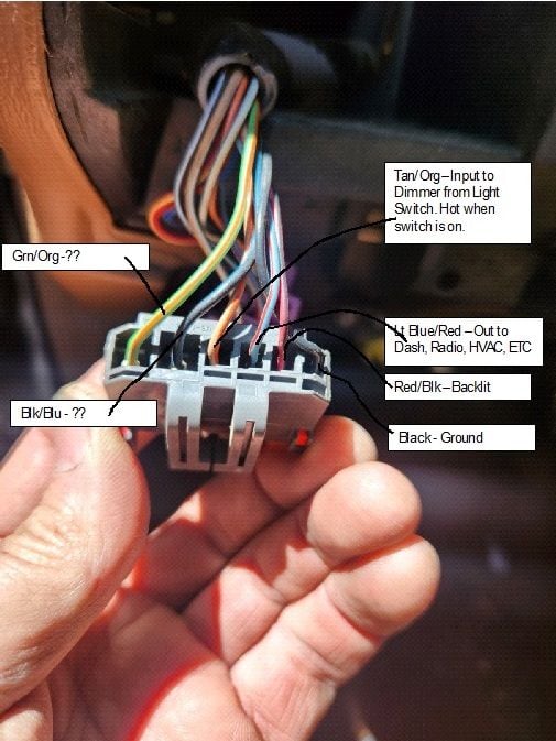
The dash light dimmer shares the same circuit as your parking lights and can develop internal resistance over time. This component often gets overlooked during standard troubleshooting procedures.
Test Dimmer Functionality
Rotate the dimmer knob through its entire range while observing the lights. If lights flicker or go out at certain positions, the dimmer mechanism is likely failing internally.
Bypass the Dimmer Temporarily
Unplug the dimmer and jumper the input and output wires together. These are usually orange and orange-black wires. If lights stay on steadily after this bypass, replace the dimmer switch immediately.
Check for Wiring Harness Chafing
The wiring harness behind the dash and firewall is prone to rubbing against sharp metal edges. This friction wears through insulation and causes intermittent shorts or open circuits.
Inspect the Firewall Pass-Through
Look at the rubber grommet where wires enter the cab from the engine compartment. Pull back the boot and inspect for worn insulation, focusing on orange, brown, and light blue wires.
Repair Method:
– Cut open damaged sections of loom to expose the wire.
– Splice in new wire using crimp connectors or solder for a permanent fix.
– Seal with heat-shrink tubing to protect against moisture.
– Reroute and secure the harness away from sharp metal edges.
Avoid: Tape-only repairs. They fail quickly under vibration and heat conditions found in trucks.
Final Fixes and Prevention Tips
Once you resolve the immediate issue, take steps to prevent recurrence. This is especially important if your truck is used for towing, off-roading, or in wet climates.
Upgrade Critical Connections
Replace the headlight switch with a Motorcraft DS-666 unit for OEM specifications. Install sealed relays in the fuse box and use dielectric grease on all lighting connectors to block moisture.
Perform Routine Electrical Maintenance
Conduct an electrical inspection every 12 months to catch issues early. Inspect fuses and relays, check ground points for corrosion, test all lights, and clean battery terminals.
Consider an Auxiliary Lighting Relay Kit
For trucks with light bars or aftermarket accessories, add a separate relay harness. This reduces the load on the factory headlight switch and prevents future overheating.
Frequently Asked Questions About F350 Parking Lights and Dash Lights Not Working
Why do my parking lights and dash lights fail at the same time?
These systems share a common power source and control path through the headlight switch or GEM module. A failure in this shared circuit causes both exterior and interior lights to stop working simultaneously.
Can a bad ground cause intermittent lighting issues?
Yes, poor grounding is a leading cause of intermittent failures in F350 lighting systems. Corroded or loose ground straps create high resistance that disrupts power flow without blowing fuses.
How do I test the park lamp relay on my Ford Super Duty?
Swap the park lamp relay with a known-good relay like the horn relay. If the lights work after swapping, the original relay was faulty and needs replacement.
Where is the GEM module located on a 1999-2003 F350?
The GEM module is located behind the left-side kick panel near the driver’s footwell. It is a black control box with multiple wire harnesses that manage body functions.
Do I need to replace the whole instrument cluster if dash lights fail?
Not necessarily. Often the issue is a loose connector, broken solder joint, or bad ground rather than a failed cluster. Inspect wiring and connections before replacing the entire unit.
Key Takeaways for Fixing F350 Parking Lights and Dash Lights Not Working
When F350 parking lights and dash lights not working issues arise, the problem almost always lies in shared circuitry. Start your diagnosis with the headlight switch and GEM connections, then methodically test power, ground, and wiring integrity.
Focus on cleaning ground points and inspecting the firewall pass-through for chafed wires. These simple steps often resolve the issue faster and avoid unnecessary part replacements. Take action today by checking your headlight switch output to begin your repair process.