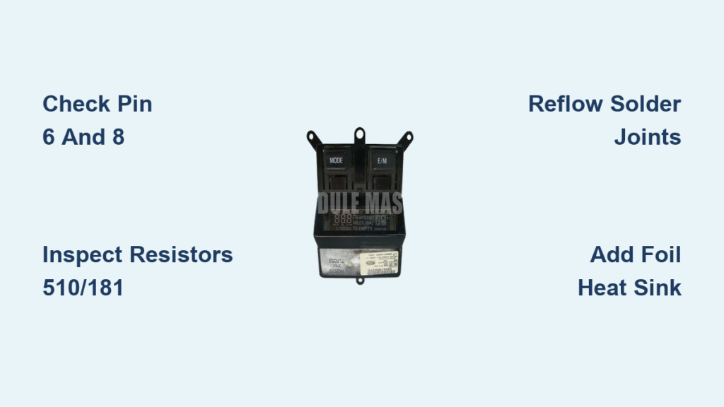
Does your 2004 F350 overhead display not working show a blank screen or incorrect temperature? This common issue stems from heat damaging internal solder joints and resistors. You do not need to buy a costly replacement unit to solve this problem.
This guide details how to diagnose and repair the fault using basic tools. You will learn to identify burnt components and reattach loose pins for under $15. Follow these steps to restore full function to your truck console.
Diagnose Why Your 2004 F350 Overhead Display Is Failing
Confirm the specific failure mode before removing the unit. This step prevents unnecessary disassembly if the issue lies elsewhere in the electrical system.
Identify Specific Screen Symptoms
Observe the display behavior when the ignition is on. Different symptoms point to different internal failures.
- Total Black Screen: Indicates power loss or detached main connector pins.
- Dim or Flickering Image: Suggests weak solder joints on critical components.
- Missing Temperature Data: Points specifically to failed surface-mount resistors.
- Unresponsive Buttons: Often caused by internal board disconnects.
Note: A very slight flicker is normal for this display technology. It represents the screen scan rate and is not a defect.
Verify Electrical Power Sources
Rule out simple fuse or wiring issues before opening the console. Check the fuse panel for the overhead accessory label. Inspect wiring near the headliner for any visible pinches. If other dash electronics work perfectly, the fault is inside the unit.
Remove the Overhead Console Safely
Accessing the circuit board requires careful removal of the plastic housing. Forcing clips will break the fragile tabs holding the unit together.
Release Side Locking Tabs
Locate the two small holes on the inner edges of the console. Insert a flathead screwdriver into each hole to depress the locking tabs. Gently pull down on one side until it releases, then repeat for the other side. Lower the unit slowly to avoid straining the ribbon cable.
Disconnect the Ribbon Cable Connector
Identify the main connector at the back of the unit. Look for a small plastic latch on the side or top of the plug. Push the latch up or down depending on your specific orientation. Wiggle the cable gently while pulling straight out to avoid damaging the connector pins.
Open the Display Housing Without Damage
Disassemble the unit on a clean surface to access the internal circuit board. Keep track of small screws and plastic washers during this process.
Remove External Mounting Screws
Turn the unit over to expose the back panel. Some models have one T10 Torx screw near the front while others have two on the sides. Remove all visible external screws to separate the main housing halves.
Access Internal Board Screws
You will see a foam pad or sticker covering internal screws. Carefully peel back the foam or make an X cut to expose the screw underneath. Remove the single T10 screw located beneath this cover to free the circuit board.
Extract the Circuit Board Module
Lift the front screen or lens off if your model requires four T10 screws. Note the location of small plastic washers before removing them. Gently pull the circuit board straight up to remove it from the housing slots.
Inspect the Circuit Board for Heat Damage

Use magnification to spot the telltale signs of failure on the green circuit board. Heat stress leaves visible marks on specific components.
Locate Burnt Surface-Mount Resistors
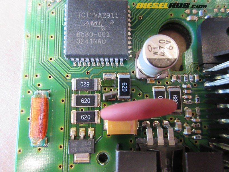
Focus your inspection on resistors near the front edge of the board. Failed resistors often turn brown or black and may appear cracked. Pay close attention to components labeled 510 and 181 as these are primary failure points.
Check Connector Pins 6 and 8
Examine Pin 6 and Pin 8 on the main connector interface. These pins frequently detach from the board due to thermal expansion and contraction. Look for visible gaps, cracks in the solder, or bent pins that do not make contact.
Identify Board Discoloration
Search for any burnt areas or cracked traces on the PCB surface. Discoloration behind components suggests long-term overheating issues. This visual evidence confirms heat as the root cause of your 2004 F350 overhead display not working.
Repair Faulty Components With Solder
Fix the root cause by reflowing cold joints or replacing damaged parts. Precision is key when working with small surface-mount components.
Reflow Cold Solder Joints
Use an 8W soldering iron with a fine tip for this task. Heat the joint for 2 to 3 seconds maximum to melt the existing solder. Do not add extra solder unless the joint looks dry or depleted. This method works for both resistors and connector pins.
Replace Damaged Resistors
Desolder any resistor that appears cracked or burnt. Replace it with a 1/8W surface-mount resistor matching the original value. Typical values include 100Ω or 1kΩ based on the code printed on the part. Solder quickly to avoid transferring excessive heat to the board.
Reattach Detached Pins 6 and 8
Apply heat to the pad and the base of the detached pin. Guide fresh solder with a fine tool to bridge the gap securely. Ensure you create a smooth, shiny joint without bridging to adjacent pins.
Add Aluminum Foil Heat Protection
Prevent future failure by installing a simple thermal upgrade during reassembly. This step addresses the root cause of thermal cycling damage.
Install a Passive Heat Sink
Cut a small piece of aluminum foil approximately 1 inch by 1.5 inches. Place it behind the circuit board covering the repaired area. This foil redirects heat away from solder joints and adhesive layers. Secure it with a tiny dot of thermal tape if needed to prevent movement.
Reassemble the Console Unit
Put everything back together carefully to ensure a secure fit. Proper alignment prevents rattling and ensures electrical connections stay intact.
Reinstall the Circuit Board
Slide the board back into its slot within the housing. Ensure the foil heat sink does not touch any live components. Reinsert and tighten the T10 screw under the foam area to secure the board.
Reattach Front Lens and Housing
Align the front screen and press it firmly into place. Reinstall the four T10 screws and plastic washers if your model uses them. Snap the front and rear clips securely to close the housing.
Reconnect and Mount the Unit
Plug the ribbon cable back in by inserting from the back then snapping down. Align the console with the ceiling slots in your truck. Push upward until you hear a distinct click on both sides indicating a lock.
Test the Repaired Display Functions
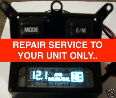
Verify the fix before considering the job complete. Ensure all features work correctly to confirm a successful repair.
Power On and Observe Screen
Turn the ignition to the On position without starting the engine. Watch for immediate screen activation upon power delivery. The display should light up evenly without dark spots.
Confirm Key Operational Features
Test the brightness to ensure it is stable and not dimming. Press the clock set, trip reset, and temperature toggle buttons. Compare the outside temperature reading to a known accurate source.
Check Physical Fit and Stability
Ensure the unit sits flush with the headliner material. There should be no rattling sounds when you tap the console gently. Rubber bumpers should prevent vibration noise if installed correctly.
Prevent Future Overhead Display Failures
Make your repair last longer than the original factory installation. Understanding why these fail helps you avoid repeat issues.
Understand Thermal Cycling Damage
The overhead console sits in the sun-facing roof and absorbs significant heat. The circuit board expands and contracts daily which stresses solder joints. Over 20 years this thermal cycling causes cracks especially on high-stress pins.
Apply Key Prevention Tips
Always use the foil heat sink as it is the number one upgrade. Avoid high-wattage irons during repair and stay under 900°F. Use 60/40 rosin-core solder for reliable and durable joints. Keep spare 1/8W resistors in your truck for future maintenance needs.
Frequently Asked Questions About 2004 F350 Overhead Display Repair
Why does my 2004 F350 overhead display show a black screen?
A black screen usually means Pin 6 or Pin 8 has detached from the circuit board. It can also indicate a blown fuse or total power loss to the unit. Check these pins first before assuming the whole board is dead.
What causes the temperature reading to disappear but the clock works?
This specific symptom points to failed surface-mount resistors labeled 510 or 181. These components regulate the temperature sensor data specifically. Reflowing or replacing these resistors usually restores the temperature function.
Can I fix the display without soldering skills?
You need basic soldering skills to reattach pins or replace resistors effectively. If you cannot solder, the repair may not last or could damage the board further. Consider practicing on scrap electronics before attempting this fix.
How much does it cost to repair the overhead display myself?
A DIY repair typically costs under $15 for a basic soldering iron and solder. This is significantly cheaper than buying a replacement unit which can exceed $550 CAD. Most materials like foil are already available in your home.
Is the slight flicker on my screen a sign of failure?
No, a slight flicker is normal and represents the display scan rate. It is not a defect unless the screen goes completely dark or dims significantly. Only worry if the flicker is accompanied by missing data or total failure.
What tools do I need to remove the overhead console?
You need a flathead screwdriver to release locking tabs and a T10 Torx driver for screws. A magnifier is highly recommended for inspecting small components on the board. Basic safety glasses are also essential for eye protection.
Key Takeaways for Fixing Your 2004 F350 Overhead Display
Repairing a 2004 F350 overhead display not working is a cost-effective solution for truck owners. Focus your efforts on resistors 510 and 181 along with pins 6 and 8. Adding an aluminum foil heat sink prevents the heat damage that caused the initial failure.
You can restore full functionality for under $15 instead of spending hundreds on a replacement. Gather your tools, follow the steps carefully, and enjoy a working console again. Your truck deserves this simple yet effective upgrade to extend its life.