A dead overhead console in your 2004 Ford F250 can be frustrating, especially when you rely on it for outside temperature, compass heading, and fuel range. This common failure typically appears between 4 and 5 years of vehicle age and stems from thermal stress caused by prolonged sun exposure. Heat melts the solder joints on the internal circuit board, causing small chips, resistors, and capacitors to detach or develop hairline cracks.
The good news? This issue is highly repairable and far cheaper than dealer replacement. Whether you choose a DIY solder fix, a professional mail-in service, or a full module swap, this guide covers every proven method. You’ll learn how to diagnose the real problem, avoid costly mistakes, and choose the most effective solution for your budget and skill level.
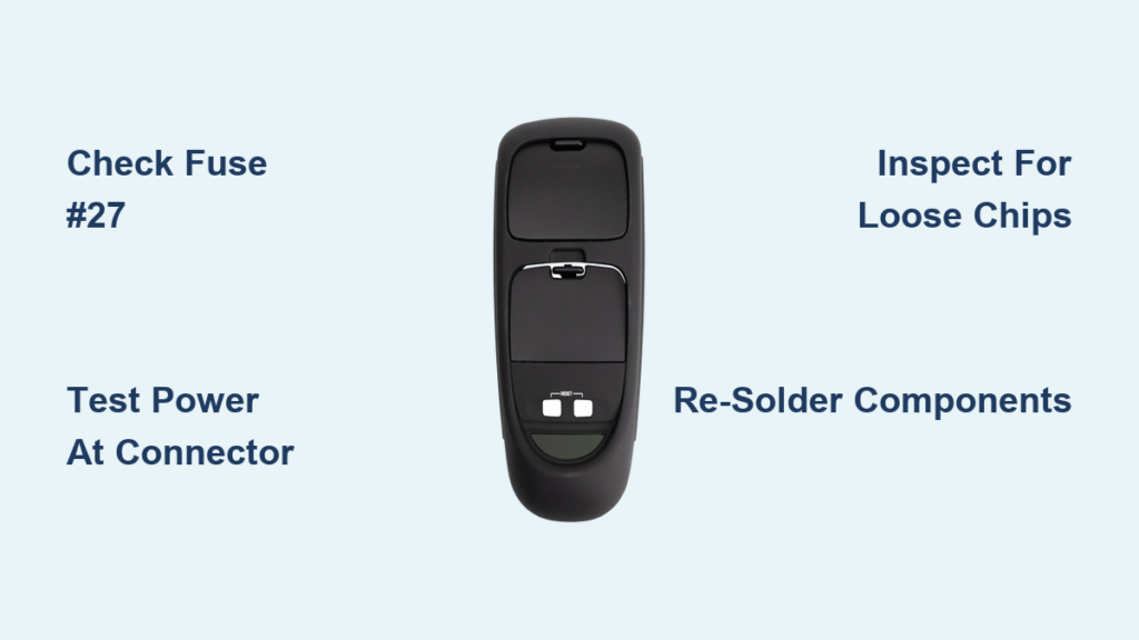
Verify Fuse #27 Before Anything Else

Before assuming the console is dead, rule out a simple fuse issue. A blown fuse can mimic total electronic failure and takes only minutes to check.
Locate and Inspect Fuse #27
Find the interior fuse box on the driver’s side dash. Identify Fuse #27, labeled “Overhead Console” or “Aux Power.” Pull it out and look for a broken filament. If blown, replace it with a 15A fuse of the same rating. If the new fuse blows immediately, you likely have a short in the wiring harness.
Confirm Power at the Connector
Even with a good fuse, test for voltage at the console’s wiring connector. Use a multimeter to probe the Red/Yellow wire while the ignition is on. You should see roughly 12V. No power means the fault is upstream in the wiring. Power present but display dead points to internal module failure.
Test Power and Ground Connections
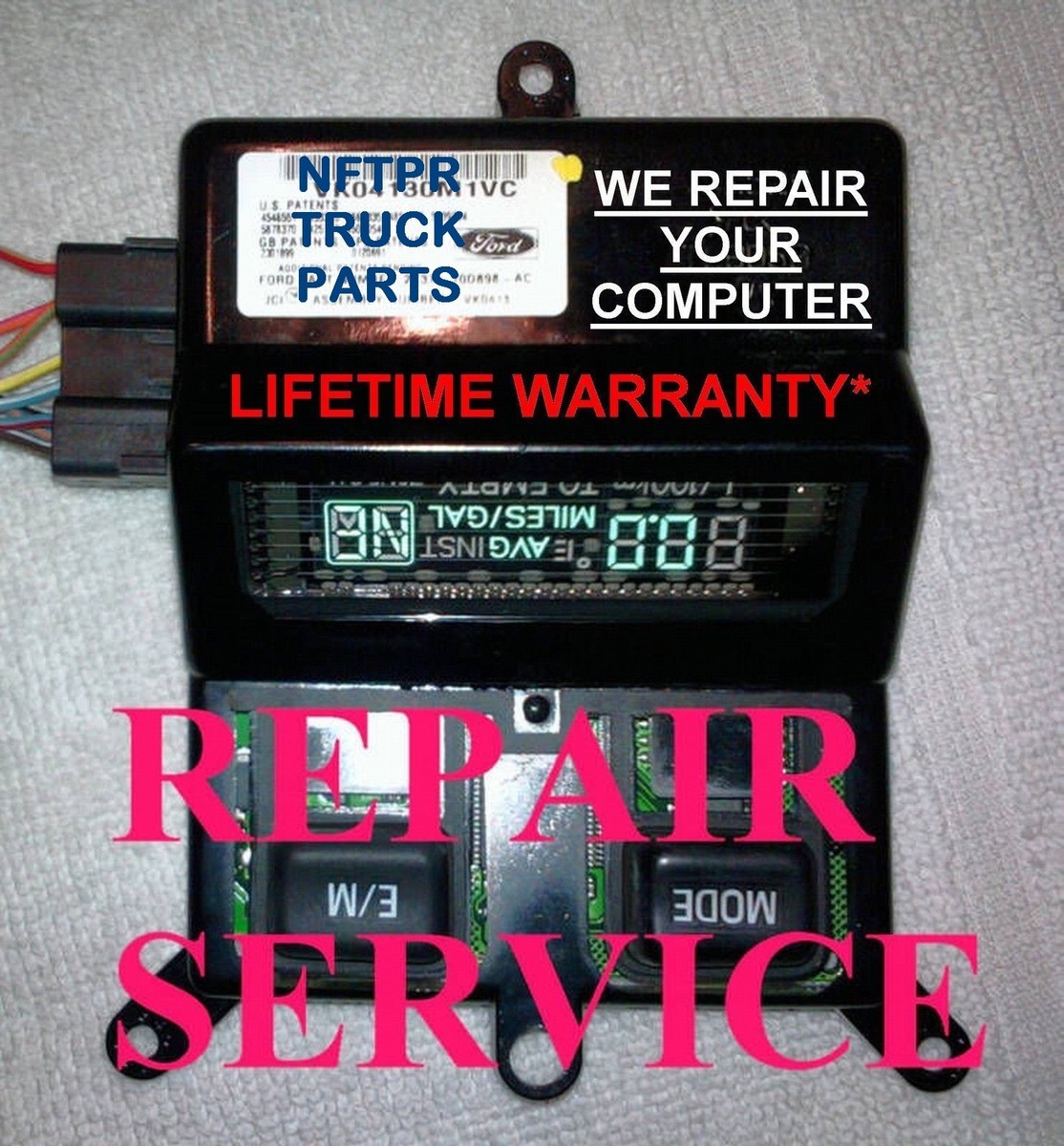
Confirming consistent power and solid grounding helps isolate whether the issue is external or internal to the console itself.
Inspect the Wiring Harness Connector
Disconnect the console’s harness and examine the pins for corrosion, dirt, or bent contacts. Clean corroded pins with electrical contact cleaner, not WD40. WD40 attracts dust and degrades over time, eventually making connections worse.
Run Voltage and Ground Tests
With the ignition on, measure voltage on the Red/Yellow wire. Expect 12V. Then probe the black or black/white ground wire against a known good ground point. You should see continuity at 0 ohms. If both power and ground check out but the display still flickers or fails, internal circuit damage is confirmed.
Perform the Tap Test for Intermittency
Gently tap the console or wiggle the connector while the truck is running. If the display flickers or briefly lights up, this is a classic sign of loose solder joints or detached components, not a wiring fault. This test alone can save you hours of unnecessary troubleshooting.
Remove and Inspect the Console Module

Once you’ve ruled out fuse and wiring issues, remove the console to inspect for visible internal damage.
Remove the Console Safely
The unit is held by plastic clips. Start at the front edge and pull downward gently to release. Avoid prying from the sides since clips break easily. Set aside the metal retaining clips carefully because you’ll need them for reinstallation.
Open the Housing and Look Inside
Use a small screwdriver or plastic pry tool to separate the housing halves. Inside, look for:
– Loose chips or capacitors resting on the board or inside the housing
– Hairline cracks in solder joints under small components
– Burnt areas behind pink capacitor disks or yellowed components
Some users notice burn marks near the display connector. Minor discoloration can be normal, but true failure signs include melted solder, lifted traces, or loose parts.
Re-solder Loose Components (DIY Method)
For many owners, the fix is as simple as reattaching a few fallen chips. This DIY method costs under $20 and takes less than an hour.
Gather the Required Tools
You will need:
– A fine-tip soldering iron (60W recommended)
– Rosin-core electronics solder
– Small pliers or tweezers
– Contact cleaner (optional)
Reattach Fallen Chips Step by Step
- Locate loose components, often 2 to 4 small black chips or surface-mount resistors.
- Match each component to its footprint on the board by looking for matching solder pads.
- Hold the component in place with tweezers.
- Heat one pad and apply a tiny amount of solder, then repeat on the other side.
- Avoid flooding joints since excess solder causes short circuits.
Reinforce Cracked Joints
Even if no parts are loose, inspect all small components. Reflow solder on any joint that looks dull, cracked, or uneven. This proactive step can prevent future failures.
Avoid These Common Solder Mistakes
- Too much heat can damage the board or lift pads
- Solder bridges between pins cause short circuits
- Loose mounting increases vibration stress on joints
Use a Mail-In Repair Service
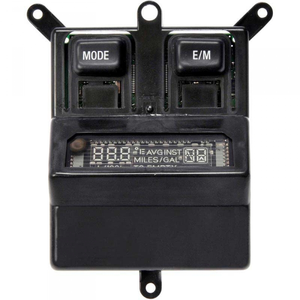
If you’re not comfortable soldering, professional repair services offer reliable fixes with warranties and upgraded components.
Compare Top-Rated Repair Providers
Circuit Board Medics ($149.99)
– USA-based in Greenville, SC
– 1-year warranty, extendable to 5 years
– 1-day turnaround, with same-day available for an extra $70
– Uses OE-spec materials and reinforces weak points
CboardRepair ($59.99)
– Lowest price option
– Claims lifetime warranty on most automotive modules
– 24-hour repair time
– Serves 1999–2008 Super Duty models
Nick’s Electronic Repair ($79.95)
– Specifically lists module 599-952
– Requires original unit shipment
– Focused on Ford overhead consoles
How Mail-In Repair Works
- Order the service online.
- Ship your defective console (customer pays outbound shipping).
- Technicians inspect, repair, and upgrade failure-prone parts.
- The unit is tested and returned, often with return shipping included.
Why Pay for Professional Repair?
Professional services use upgraded components that resist future heat damage, offer warranty protection against recurrence, and require no technical skill on your part. This option is ideal for intermittent failures or complex board damage.
Replace the Console Module Entirely

When the circuit board is burnt, cracked, or beyond repair, full replacement is the best path forward.
Buy a Compatible Replacement Unit
Look for part number 599-952 or “2004 F250 Overhead Console Module.” Your options include:
– Aftermarket new: Around $200 on Amazon, eBay, or auto parts stores
– Refurbished: May include a repair warranty
– Dealer units: $500 to $1,500, usually unnecessary
Ensure compatibility with 1999–2008 Super Duty trucks. Newer updated versions offer better heat resistance.
Install the New Console
- Transfer all metal clips from the old unit to the new bezel.
- Snap the new console into the headliner and listen for secure clicks.
- Reconnect the wiring harness.
Calibrate the Compass After Installation
Any power interruption resets the compass. To recalibrate:
1. Turn the ignition to “Run.”
2. Press and hold the “Reset” or “Mode” button until “CAL” appears.
3. Drive slowly in tight circles until calibration completes, usually after 2 to 3 rotations.
Prevent Future Console Failures
Even after a successful repair, heat remains the primary threat. Take these steps to extend your console’s lifespan.
Reduce Heat Exposure
Park in the shade whenever possible or use a windshield sunshade. You can’t eliminate cabin heat entirely, but reducing peak temperatures significantly lowers thermal stress on the board.
Secure Clips to Reduce Vibration
Ensure all metal clips are installed and tight. Loose mounting increases vibration stress on solder joints and accelerates failure.
Clean Connectors Properly
If you ever disconnect the unit, clean contacts with electrical contact cleaner, never WD40 or other lubricants.
Monitor for Early Warning Signs
If flickering returns, catch it early. A second round of soldering or an upgrade to a professionally repaired unit may be needed before total failure occurs.
Common Mistakes to Avoid
Even experienced DIYers make errors that lead to repeat failures. Steer clear of these pitfalls.
Ignoring Clip Damage
Broken plastic clips cause rattling and poor mounting, increasing stress on the circuit board. Replace missing clips or transfer metal ones carefully during every repair.
Using WD40 on Connectors
WD40 is not a contact enhancer. It attracts dirt and dries out over time. Always use dedicated contact cleaner instead.
Over-Soldering Joints
Excess solder can bridge pins and short the board. Use a fine tip and apply minimal solder to every joint.
Skipping Compass Calibration
After any repair, the compass won’t work until recalibrated. Don’t assume the unit is broken. Just drive in circles to complete the process.
Assuming a Backup Battery Exists
There is no watch battery in the 2004 F250 console. Power loss resets settings, but the underlying issue is always electronic, never a dead battery.
Match the Repair Method to Your Situation
Not every fix fits every situation. Choose based on your symptoms, skills, and budget.
Choose DIY Solder Repair If:
- You found loose chips inside the housing
- You have basic soldering tools and experience
- Cost is your top priority
- You accept some risk of recurrence
Choose Mail-In Repair If:
- You want a warranty for peace of mind
- The board shows visible heat damage
- You lack soldering experience
- You need a long-term, reliable fix
Choose Full Replacement If:
- The PCB is burnt or physically cracked
- The display glass is damaged
- You’re replacing a failed DIY attempt
- You want plug-and-play simplicity with no soldering
Frequently Asked Questions About 2004 F250 Overhead Console Repair
What causes the overhead console to stop working in a 2004 F250?
Thermal stress from prolonged sun exposure melts the solder joints on the internal circuit board. This causes small chips, resistors, and capacitors to detach or develop hairline cracks, leading to display failure.
Is there a fuse for the overhead console?
Yes. Fuse #27 in the interior fuse panel powers the overhead console. Always check this fuse first before pursuing more complex diagnostics.
Can I repair the overhead console myself?
Yes. Many owners successfully re-solder loose components using a fine-tip soldering iron and minimal solder. The repair typically costs under $20 and takes less than an hour for those with basic soldering skills.
How much does professional repair cost?
Mail-in repair services range from $59.99 to $149.99, depending on the provider. This is significantly cheaper than dealer replacement, which can run $500 to $1,500.
How do I recalibrate the compass after repair?
Turn the ignition to “Run,” press and hold the “Reset” or “Mode” button until “CAL” appears, then drive slowly in tight circles until calibration completes, usually after 2 to 3 rotations.
Does the 2004 F250 console have a backup battery?
No. There is no watch battery in this model. Power loss simply resets the compass and other settings, but the failure itself is always electronic or mechanical, never a dead battery.
Key Takeaways for 2004 F250 Overhead Console Repair
The 2004 F250 overhead console failure is predictable, preventable, and almost always fixable. Heat is the root cause, and early diagnosis saves money. Start by checking Fuse #27 and testing power at the connector before assuming internal damage. If you find loose chips, a DIY solder repair costs under $20. If the board shows heat damage or you’re not comfortable soldering, a mail-in service offers warranties and upgraded components for $60 to $150. Full replacement runs around $200 and is best reserved for physically damaged boards.
Your next step is simple: pull Fuse #27 right now and verify it’s intact. If the fuse is good, test for power at the Red/Yellow wire. Once you’ve confirmed the fault is internal, choose the repair path that matches your skills and budget. Don’t live without your temperature readout or compass when a proven fix is within reach.