Your Ford F-150 starts overheating in traffic. The A/C blows warm at stoplights. You pop the hood and hear dead silence. The radiator fan is not spinning. This is a common but serious issue, especially in F-150 models from 2009 to 2016. Left unchecked, it can lead to engine damage, failed A/C performance, and expensive repairs.
The root cause usually lies in the electrical system, not the fan motor itself. Your dual electric fans rely on a precise series-parallel circuit controlled by relays, fuses, and the PCM. A single blown fuse or failed relay can shut down both fans, even if the motors are perfectly fine.
Check Critical Fuses First
Fuses are the most common failure point. A single blown fuse can disable the entire cooling system, so start your diagnosis here.
Test Fuses 12, 15, 63, and 30
Open the underhood battery junction box (BJB) and the cabin fuse panel. Use a multimeter to test each fuse for continuity. Check for voltage drop under load if possible.
Key fuses to inspect:
- Fuse #12 (10A): Powers the low-speed fan relay. No power here means no low-speed operation.
- Fuse #15 (40A): Feeds high-speed relay and Fan #2 directly. Blown means no high-speed fan.
- Fuse #63 (25A): Completes the series path from Fan #1 to Fan #2. If open, Fan #2 will not run in low speed.
- Fuse #30 (5A): Located in the left dashboard junction box. Powers the climate control module. If blown, the PCM never gets the A/C on signal, so the fan will not activate.
Pro Tip: If a fuse blows immediately after replacement, suspect a short to ground or a failed fan motor drawing excessive current.
Replace only with identical amperage fuses. Never jump a fuse or use a higher rating.
Test Cooling Fan Relays

Relays control fan speed stages. A failed relay stops fan operation instantly, so testing them is essential.
Locate and Identify Key Relays
All relays are in the underhood BJB. Refer to the diagram on the fuse box cover for your exact locations.
Critical relays to test:
- Relay #5: High-Speed Fan Relay
- Relay #40: Main Cooling Fan Relay
- Relay #85: Low-Speed Fan Relay
- Relay #3 (2016 2.7L EcoBoost): Right-Fan Control Relay, a common failure point
Swap Test: Quick Relay Check
Turn off the engine. Pull out Relay #85 (low-speed). Replace it with a known-good relay of the same type, such as the horn relay or A/C clutch relay. Start the engine, turn on the A/C, and wait 2 to 3 minutes. Listen for fan engagement.
If the fan spins now, the original relay was bad. You should hear a click when the relay engages, followed by fan noise.
Multimeter Test: Confirm Relay Health
Set your multimeter to ohms (Ω). Test coil terminals (typically 85 and 86). Normal readings are 70 to 110 ohms. Infinite resistance means an open coil (dead relay). Near-zero resistance means a shorted coil.
Test contacts (30 and 87) by applying 12V to the coil. You should see continuity. No continuity indicates pitted or welded contacts.
Expert Note: Relays fail from heat cycling and moisture. Use Motorcraft or OEM-spec relays. Cheap aftermarket units fail faster.
Bypass Relay to Test Fan Circuit
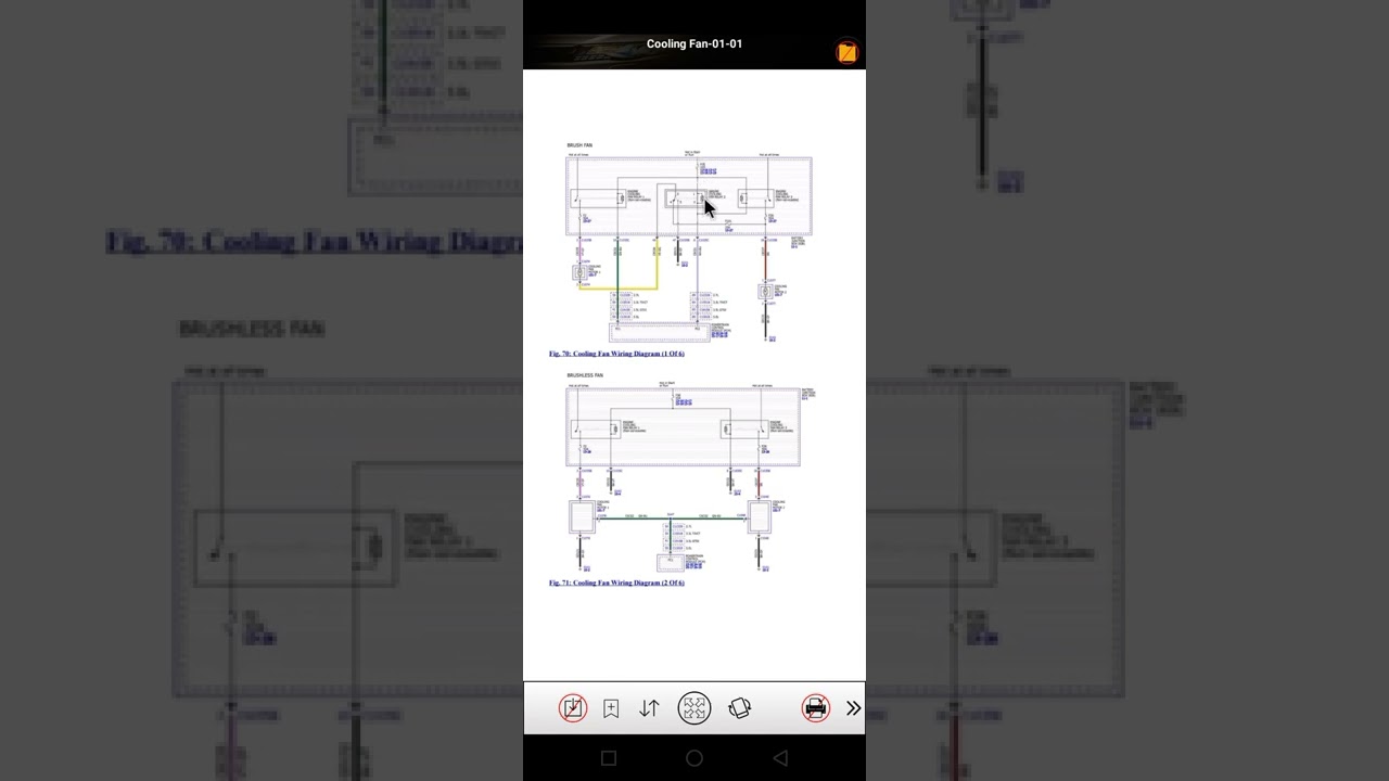
If relays seem fine, test the fan and wiring directly using a jumper test.
Jumper Test: Low-Speed Circuit
Disconnect Relay #85. Use a fused jumper wire (10A fuse inline). Connect terminal 30 to terminal 87 on the relay socket. Observe the results.
| Result | Diagnosis |
|---|---|
| Both fans spin | Circuit and motors are good. Problem is in relay or control signal. |
| Only Fan #1 spins | Check Fuse #63, wiring between fans, or Fan #2 motor. |
| No fans spin | Problem in power supply, ground, or both motors. |
Warning: Always use a fused jumper. A direct short can melt wires or damage the PCM.
Test Fan Motors Directly
Even with proper power, a bad motor will not spin. Test each fan independently.
Apply 12V to Each Fan
Disconnect the fan motor connector. Connect the positive lead from the battery to the fan positive terminal. Ground the negative terminal to battery negative. Watch for rotation.
What to look for:
- Immediate spin means the motor is functional.
- No spin means an internal open circuit or seized bearing.
- Jerky or slow spin means worn brushes or a partial short.
Measure Current Draw
Use a multimeter in ammeter mode. Normal current draw is 20 to 30 amps per fan. Over 35 amps indicates motor binding or an internal short. Under 15 amps indicates an open winding or poor connection.
Pro Tip: If one fan draws high current, replace it. Overloaded motors stress relays and fuses.
Inspect Ground Connections
Poor grounding causes intermittent or no fan operation. This is often overlooked but critical.
Locate Key Ground Points
Ground points G101 and G102 are located under the battery tray and under the Battery Junction Box respectively.
Test Ground Resistance
Set your multimeter to ohms (Ω). Place one probe on the negative battery terminal. Place the other probe on G101 or G102. Read the resistance.
| Reading | Condition |
|---|---|
| Less than 0.5 Ω | Good |
| More than 1 Ω | Poor. Clean or replace. |
Fix a bad ground:
- Remove the bolt.
- Sand contact surfaces to bare metal.
- Apply dielectric grease.
- Reinstall and tighten.
Visual Cue: Corroded, green, or loose ground straps are red flags.
Use a Scan Tool to Command Fans
A cheap code reader will not cut it. You need active command capability to properly diagnose this system.
Why FORScan is Essential
FORScan is free software for Windows with an OBD2 adapter. It reads live data including coolant temperature, A/C pressure, and fan status. It can command fans manually, forcing low or high speed. It also checks for U0284 DTC (AGS communication loss).
Steps to command fans:
- Connect your OBD2 tool.
- Open FORScan.
- Go to PCM, then Active Commands, then Cooling Fan.
- Select Low Speed, then High Speed.
- Observe fan response.
If fans run when commanded, the issue is in sensors or PCM logic, not wiring. If no response, suspect fuses, relays, grounds, or PCM driver failure.
Check Coolant and A/C Sensors
The PCM will not turn on the fan without correct input from multiple sensors.
Monitor Engine Coolant Temperature (ECT)
Normal fan trigger is approximately 220°F for low speed and 235°F for high speed. If the gauge shows overheating but the fan does not run, check the ECT sensor reading via scan tool, wiring to the sensor for opens or shorts, and coolant level and thermostat function.
Warning: A faulty ECT sensor can report cold when the engine is hot, preventing fan activation.
Verify A/C Refrigerant Pressure
Low refrigerant mimics fan failure. At 100°F ambient temperature, normal low-side pressure is 65 to 70 psi. Normal high-side pressure is 375 to 400 psi. If low-side reads 35 to 40 psi, the system is undercharged.
Result: A/C cycles off, fan does not engage, and cooling is poor at idle.
Fix: Evacuate the system, recharge to OEM-specified weight, add UV-compatible dye (no refrigerant carrier) to find leaks, and replace Schrader valves, which are a common leak source.
Diagnose Active Grille Shutter (AGS) Faults
Newer F-150s use AGS to control airflow. A failure can delay fan activation.
Look for DTC U0284
U0284 means Lost Communication with Active Grille Shutter Module. It does not always trigger a check engine light but can disable coordinated fan logic.
Test with FORScan:
- Command the shutter open and closed.
- Listen for actuator motor noise.
- Inspect for binding or debris.
After a front-end collision, check shutter blades for misalignment, inspect harness routing through the radiator support, and look for chafed wires near the actuator.
Fix: Recalibrate, repair harness, or replace the AGS module.
Decode Common DTCs
Check for stored codes, even without a check engine light.
| DTC | Meaning | Likely Fix |
|---|---|---|
| P0480 | Fan 1 Control Circuit | Relay #85, Fuse #12, wiring |
| P0481 | Fan 2 Control Circuit | Relay #5, Fuse #15, Fan #2 motor |
| P0645 | A/C Clutch Relay Circuit | Fuse #30, relay, PCM signal |
| U0284 | AGS Communication Loss | Wiring, module, recalibration |
P0480 and P0481 together often mean failed relays or blown fuses, not bad fans. Clear codes after repair and retest.
Fix Series-Parallel Circuit Failures
Dual fans use series wiring for low speed and parallel for high speed. Understanding this is crucial.
Why One Bad Fan Kills Low-Speed Mode
In low speed, power flows from Battery to Relay 85 to Fan #1 to Fuse #63 to Fan #2 to Ground. If Fan #1 fails open or Fuse #63 is blown, Fan #2 gets no power.
Test:
- Jumper Relay #85 (terminal 30 to 87).
- If only Fan #1 spins, check Fuse #63, wiring between fans, and Fan #2 motor.
High-Speed Mode Relies on Multiple Relays
Relay #5 (high-speed) and the Control Relay must engage. Fan #2 gets direct power from Fuse #15. Both fans run at full speed in parallel mode.
Failure Point: Relay #3 on 2.7L EcoBoost models often fails and prevents the right fan from powering up.
Prevent Future Failures
Do not just fix it. Make it last.
Best Practices
Replace Schrader valves every time A/C is opened. Use dielectric grease on relay and fuse contacts. Clean the fan shroud annually, as debris can reduce airflow by up to 50%. Inspect wiring after off-road or collision damage. Use OEM or Motorcraft relays, as aftermarket units fail early. Verify thermostat compatibility, as aftermarket stats may open too late.
Pro Tip: A fan that runs after key-off indicates a stuck relay (welded contacts). Replace immediately.
Final Diagnostic Checklist
Use this sequence to pinpoint the issue fast:
- Spin fans by hand. Seized? Replace.
- Check fuses: #12, #15, #63, #30.
- Swap relays: #5, #40, #85, #3.
- Jumper Relay #85. Do fans run?
- Apply direct 12V test. Confirm motor function.
- Test grounds G101 and G102. Must be less than 0.5 Ω.
- Scan for DTCs using FORScan.
- Command fans. Force low/high speed.
- Check A/C pressures. Recharge if low.
- Verify AGS function. Look for U0284.
Frequently Asked Questions About F-150 Radiator Fan Not Working
Why does my F-150 radiator fan not work at idle but works at highway speeds?
This typically indicates low refrigerant charge or a failing low-speed relay. At idle, there is no natural airflow through the radiator. The fan must provide all cooling. If refrigerant is low, the A/C system cycles off, reducing condenser airflow and causing overheating. Test A/C pressures and inspect low-speed relay #85.
Can a bad thermostat cause the radiator fan not to work?
Yes. If the thermostat stays closed, coolant never reaches normal operating temperature. The PCM may not signal the fan to activate. Conversely, a thermostat stuck open can cause constant low-temperature operation. Verify thermostat function and replace with OEM-spec units.
How much does it cost to replace a radiator fan on an F-150?
OEM fan assemblies cost $200 to $400 each. Labor adds $100 to $200 if professional installation is needed. Relays cost $20 to $50 each (OEM). Fuses are under $10. Most fan failures are relay or fuse-related, not the motor itself.
Will driving with a non-working radiator fan damage my engine?
Yes. Continued operation without proper cooling can cause overheating, head gasket failure, and engine damage. If the fan is not working, monitor coolant temperature closely. Avoid heavy loads, towing, or idling in hot weather. Repair immediately.
Why does my F-150 fan run after I turn the engine off?
This indicates a stuck relay with contacts welded shut. The relay is feeding power to the fan even with the ignition off. Replace the stuck relay (usually Relay #85 or #5) with an OEM-spec unit. This is a common issue on F-150 and Ford Edge platforms.
Can I fix the radiator fan myself, or do I need a professional?
Most electrical diagnoses are DIY-friendly with basic tools and a multimeter. Fuse, relay, and ground testing are straightforward. Scan tool diagnostics with FORScan require a laptop and OBD2 adapter but are manageable for beginners. Complex wiring repairs or PCM issues may require professional help.
Key Takeaways for Fixing Your F-150 Radiator Fan
When your F-150 radiator fan is not working, start with the simplest fixes first. Blown Fuse #30 (5A) in the cabin kills the A/C signal entirely. Failed Relay #85 or #5 stops fan operation with no click. Open Fuse #63 kills Fan #2 in low-speed mode. Bad ground at G101 or G102 causes intermittent operation. Low refrigerant charge mimics fan failure. AGS fault (U0284) disrupts cooling logic.
The dual-fan system is interdependent. One failure can knock out both fans due to series wiring in low-speed mode. Use FORScan, test circuit by circuit, and verify sensors and refrigerant to avoid misdiagnosis. Fix it right with OEM parts, and your F-150 will stay cool whether idling in traffic or towing uphill.